After downloading a file, it is often Blocked. You must right-click on it, pick Properties and then check the Unblock item: But doing a dozen or more files gets old, real fast. I just learned a way to Unblock a batch of files at once. It involves using PowerShell, a Microsoft tool that is a…
If you want to use a new type of hanger, or are a fab shop that gets a job from a contractor that uses a hanger type that you do not have, it is easy to add that new hanger type to your own machine. A hanger is an assembly, and an assembly is just…
Recently our previous blog service (Typepad) ended their business – so, we have a new home. It will take a bit to get images back and displaying properly, but we are working on it! Final pageview count of original Typepad blog: 387,232
I have a quick question. How to I list 001 Victaulic 90’s and 009 Victaulic Couplings? Is there an equivalent? I cannot seem to locate them in HydraLIST
The answer depends on which program is being used:
Using AutoList from HydraCAD:
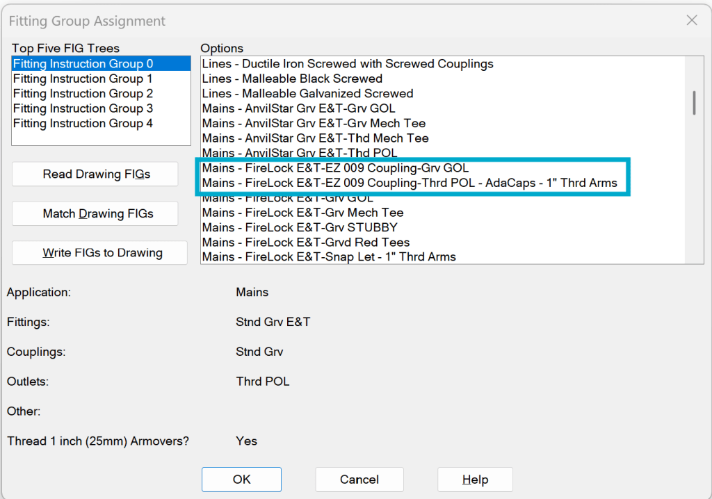
Change your fitting mapping to one of the available Firelock Fitting with 009 Coupling Groups – that’s all it takes
In HydraLIST:
All of the part numbers for these fittings are included in the standard part number database.
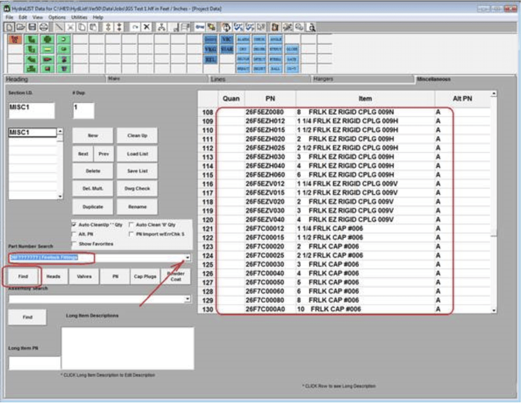
In the MISC Input – key in 009 or 26F Firelock Fittings into the Search field and pick FIND to display all the fittings. Enter quantities and select Clean Up when done to remove those items that are not quantified
You buy an Autodesk Subscription, but are stymied when trying to install it on a user’s machine? Yeah, so are a lot of people. Autodesk does not do a good job of explaining how user access works, IMHO.
Here is a typical scenario:
ABC Sprinkler Company buys two AEC Industry Collections. Johnny B. is the Contract Manager. He got that designation by being the one who ordered the software or who we understood to be the one who is going to handle the deployment of the software. He downloads the software from Autodesk Account and puts the install files on the company server. He then tells Bobby D. to install it. Bobby does so, but cannot actually use the software because he is told…
Contact your administrator to request permission to use this product.
…when he tries to use it. What happened?
This page from Autodesk explains it a bit, but i will try to go further than that.
Why did it fail?
Because each user must be specifically and explicitly given access to each product they are expected to use.
Why does Autodesk do this?
Because without user access being specified, users would be able to ‘hoard’ as many products as are available (i.e. AutoCAD, Revit, Navisworks), possibly leaving those that really need it out in the cold.
What must be done?
User Access must be granted. This is done by the Contract Manager. They must log into their Autodesk Account and give the users access. Tips on using the Autodesk Account can be found on this earlier post: Navigating Autodesk Account
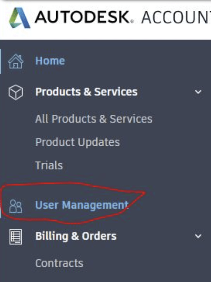
1. From the list at left, Pick User Management:
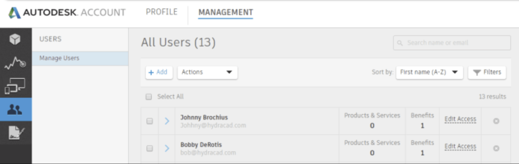
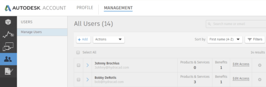
2. A list of users will appear:
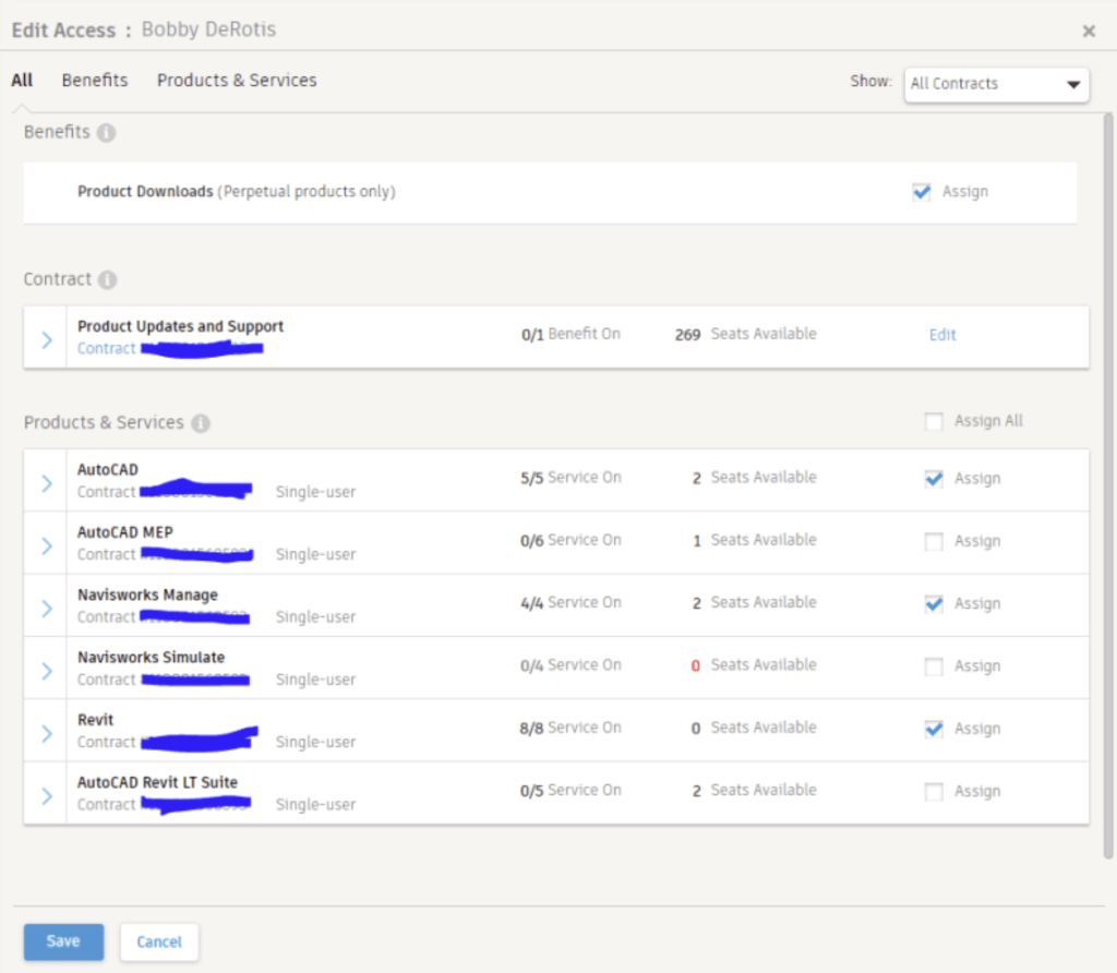
3. Pick Edit Access for the user you are working with. Check the Assign box for all products you want to give them access to
4. Pick Save. In a few moments the User screen will update with the Products and Services showing the number of programs they can access
There are many ways of adding loose material and kits to a HydraCAD drawing in order to get them listed. Some are old(er) and many are newer. All of these are on the Listing Toolbar. These do not need to be attached to pipes or sprinkler heads in order to have them list. They simply need to be inserted within the system boundary you are using (if one) on your drawing.
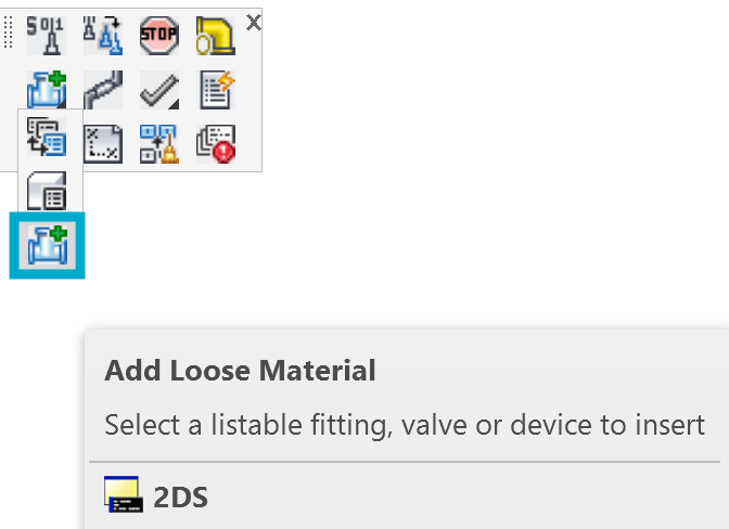
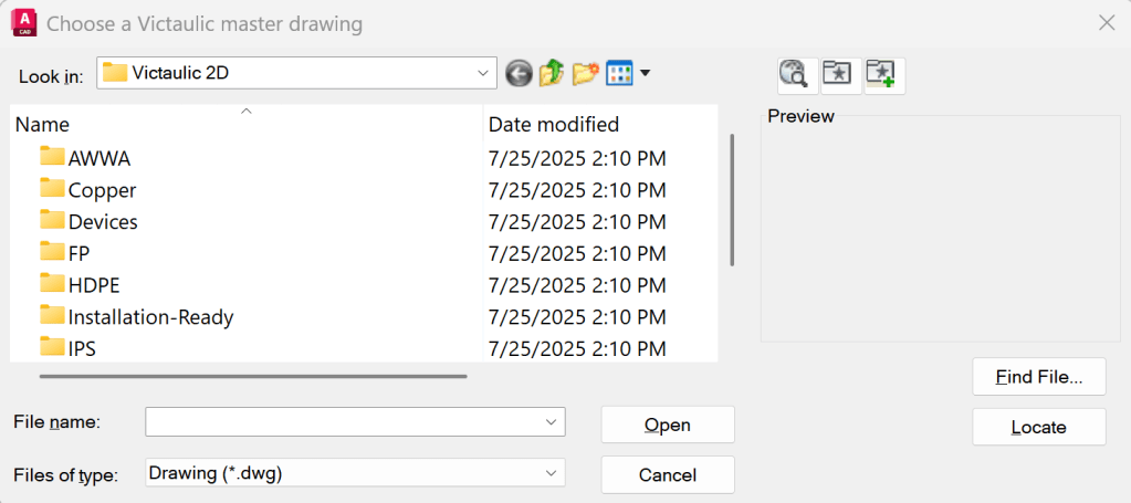
The first one of these is the Add Loose Material (2DS) command found on the fly-out associated with the fifth button on the Listing toolbar.
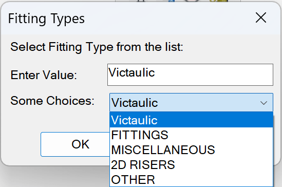
This command includes a diversity of items, of which three are listable:
A complete set of Victaulic master details, courtesy of that manufacturer – not listable
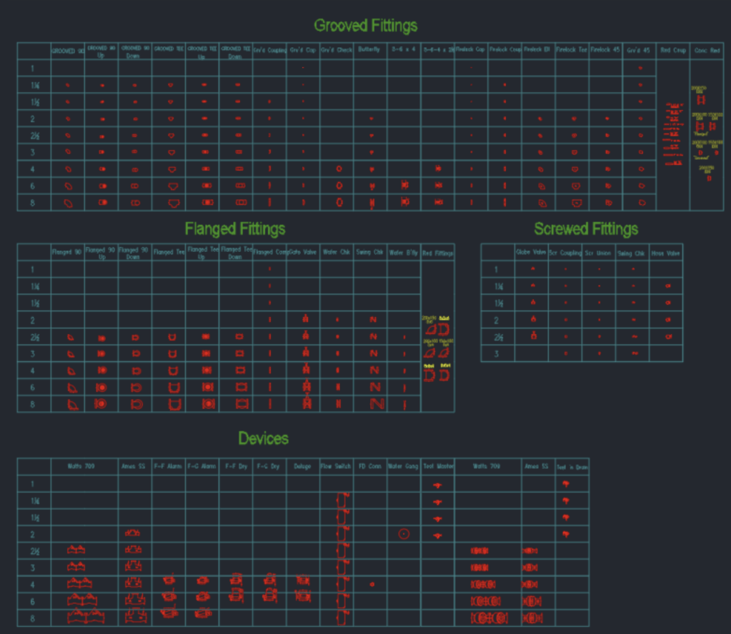
A table of 2D fittings and valves
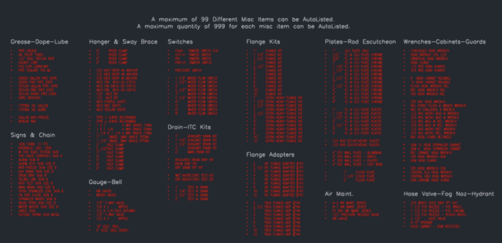
Miscellaneous loose items and kits
Prebuilt 2D Risers
Victaulic Master Details
These details were furnished by the Victaulic Corporation. They include a library all of their water supply and fire sprinkler valves and fittings. Insert these as needed into the drawing. Please note – these details will not be picked up by the AutoList command
Loose Fittings
This command opens up a drawing containing many individual valves and fittings. These are AutoList ready. Simply copy and paste them from the opened drawing into your drawing, or right-click and drag and drop them from here to there.
Miscellaneous Fittings
Opens up a different drawing, from which items can be copied and pasted exactly like the Loose Fitting command above. However, unlike the Loose Fittings command, these are not graphic details, but blocks containing text.
These ‘details’ are notable in that:
The text is not text but a block that uses text as it’s attribute
The text used corresponds to the part or kit as it is defined, by default, in HydraLIST
The part number corresponding to the text description is also contained within the block, as is the diameter, if relevant
Take a look at the upper left of the Misc-Items drawing:
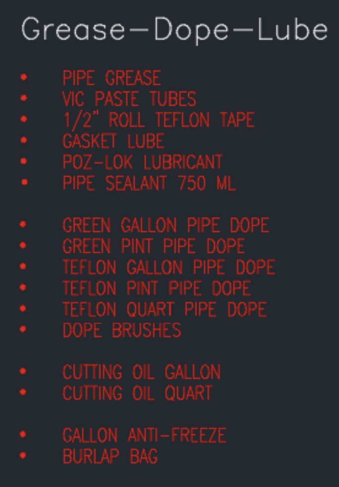
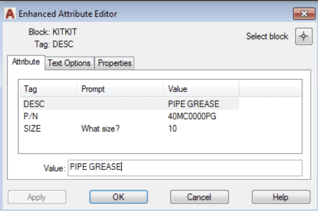
Double click on the PIPE GREASE item, below
Note the DESCription and the Part Number (P/N) (and SIZE). If you were to look at the data in HydraLIST, you would find this part listed under that number.
Again, select the items you want to list and copy and paste (or drag and drop) into your drawing to have them listed.
Note: You can make your own additions to this archive of items by copying and pasting any one of the text/blocks to another location in the Misc-Items drawing. Then, just double click and change the settings to something you want to list, keeping in mind that the P/N is how it finds the items in HydraLIST, not the description.
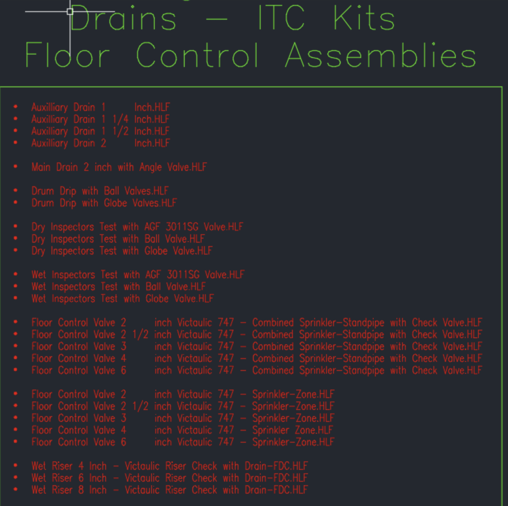
Looking at the right side of the Misc-items drawing, you will notice not individual items, but kits.
Likewise, these work just like the individual items at left (and described just above) but they correspond to kits or assemblies of items, also defined in HydraLIST.
2D Risers
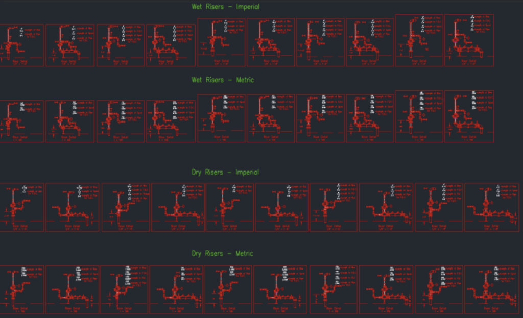
This is an older command, but one that works like the above two commands. It contains risers that are pre-built for both Imperial and Metric unit systems, Wet and Dry. This command has largely been superseded by the 3D Riser tools found in the toolbar of the same name.
Again, copy and paste, or drag and drop these in your drawing.
“I have a question about modifying hanger symbols. Here’s the issue, many times the Lister’s complain that our plans are too busy, because pipe diameters lay over hanger numbers, etc. I know we can use the auto cleanup but I really want to eliminate the hanger # & either modify an existing symbol or add a new one let’s say an X instead. Then I want to be able to access it from the menu in setup, is that possible & how do I go about it?”
Modifying the hanger is a different issue – I will go over that at some time in the future. But, right now, there is a lot that can done concerning the data shown by the hanger!
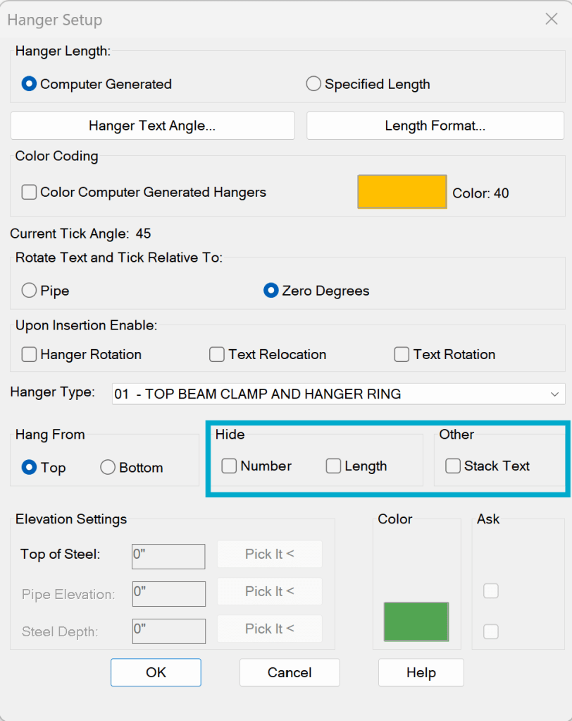
Here we have the Hanger Setup dialog box:
Note the three check boxes circled.
The first two let you hide the following:
Hanger Number (#3, i.e.) Hanger Length (1-0), i.e.) Both Hanger Number and Length (showing just the tick mark)
The third check box lets you show the info, but reduce the footprint of the text by stacking it
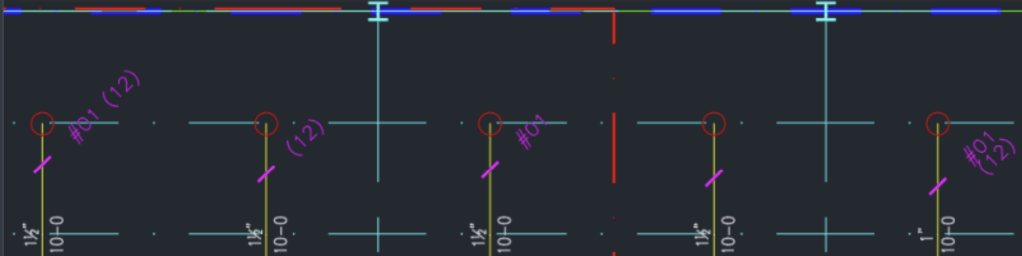
Some pictures of what these look like:
From left to right:
Nothing Hidden Number Hidden Length Hidden Number and Length Hidden Nothing Hidden, but with Stack Text checked
One or more of these should take care of the problem
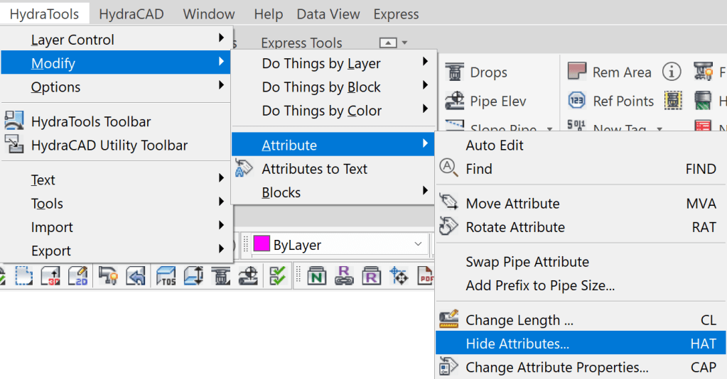
Note: If you change your mind about the display of these attributes, you can always change it later by using the Hide Attribute (HAT) command found in the HydraTools menu. This command can also be used to Unhide the Attributes:
If you have a drawing with paragraphs of text all written in individual lines, you may find it troublesome to change the fonts, size of text, add formatting, or, heavens forbid, adjust the room the paragraph takes up. These individual lines are composed of old-school text tools like Dynamic Text (DTEXT), or regular text (TEXT).
Multiline text (MTEXT) is far superior in all ways. You can create several paragraphs of text as a single multiline text (mtext) object. With the built-in editor, you can format the text appearance, columns, and boundaries. But, what if you don’t feel like retyping existing TEXT into MTEXT?
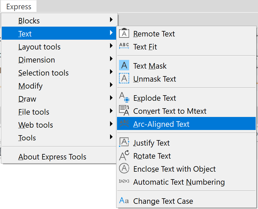
Express Tools to the rescue. Pick Express Tools, then pick Text. You will find the Convert Text to Mtext command there. Just select the text to convert, and it is converted!
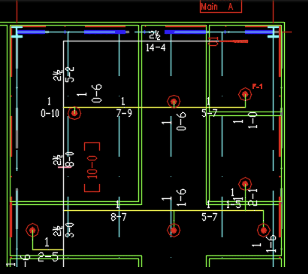
Some couplings result in a 1/8″ or more pipe separation, after they are added to pipe. On long runs of pipe, the multiple separations accumulate, and result in a pipe that is too long overall. For example, a run of pipe with 16 couplings can result in the pipe creeping 1/8″ per coupling for a total of 0-2″. A pipe segment somewhere in the run of main should be adjusted 2″ shorter so the overall main length will be correct.
The example below shows mains that are a total of 168′-0″ long from end to end. The main on the bottom has couplings cut in at exactly 10′-6″ – resulting in 16 pieces exactly 10′-6″ long. The main on the top has couplings cut in at 10′-6 1/8″ – resulting in 15 pieces rounded to 10′-6″ long and 1 piece 10′-4″ long. Pipe dimensions are rounded to the nearest 1/2″ or 1/4″ so the extra 1/8″ in each pipe segment does not show up in the reported length. The INSTALLED length of both mains will end up being 2″ longer than the total of the added “pipe length dimensions”.
After installation the bottom main will be 168′-2″ long.
After installation the top main will be 168′-0″ long as required.
Many companies keep their HydraLIST database pricing current, at least to the best of their abilities given how often prices change. If you enter a part number into HydraLIST, the pricing gets pulled up when the list is processed. If you use certain parts regularly, it makes sense to update the HydraLIST Database with those prices. This can be done one-by-one or with one of the Wizard in HydraLIST.
But what if you just need to add some items that you only use once in a while, and don’t feel like adding to the database. Can those be priced? Yes, they can.
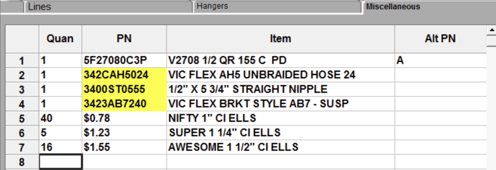
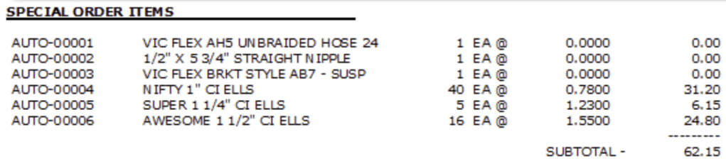
On the Miscellaneous tab enter in the Quantity and Item descriptions. Instead of typing in the (non-existent) part number, type in the price instead, as seen below:
When the list is processed (assuming at least one of the pricing reports is turned on), these items will be priced under the Special Order Items, with the prices extended.
Note, however, that the items are not grouped with like items, but are instead tossed into the Special Order Items category. If you want them to show up with their buddies, then define them in the database.
‘I had a question about center to center dimensions on pipe. We do tons of CPVC, and the ½” increments aren’t necessary. Can I force 1” increments on the center to center dimensions?”
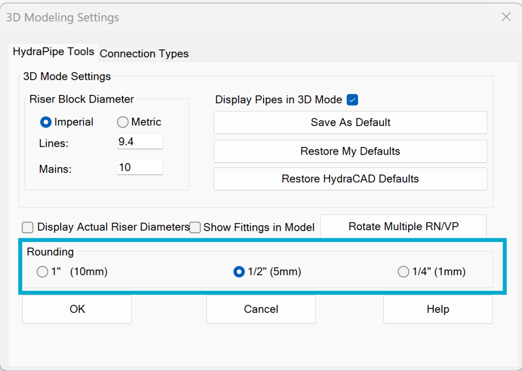
This can be done by setting the default drawing pipe dimension rounding to the nearest inch. The pipe must be sized before this process is begun.
Pick 3D Modeling Options (3MO) from the 3D Modeling toolbar:
Pick the HydraPipe Settings tab and set the Rounding to 1″. Pick Apply:
Raise the drawing to 3D. When it is brought back to 2D, you will see the pipe sizes are now to the nearest inch:
I had no idea this command existed, but found it when looking for a better way to rename a layer after a customer reported an error while running an AutoList.
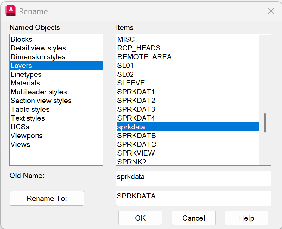
The cause of the error was that the pipe block layer, SPRKDATA, was built in the drawing as sprkdata (lower case). While may of HydraCAD’s routines are trained to work with either lower or upper case names, this routine was not.
Enter the RENAME command. As you can see from the dialog below, you can use it to rename many things in the drawing.
There are also command line options, to automate the renaming of many layer at once, for example. Such a procedure will be added to checkups in a future HydraCAD update, to eliminate such problems.
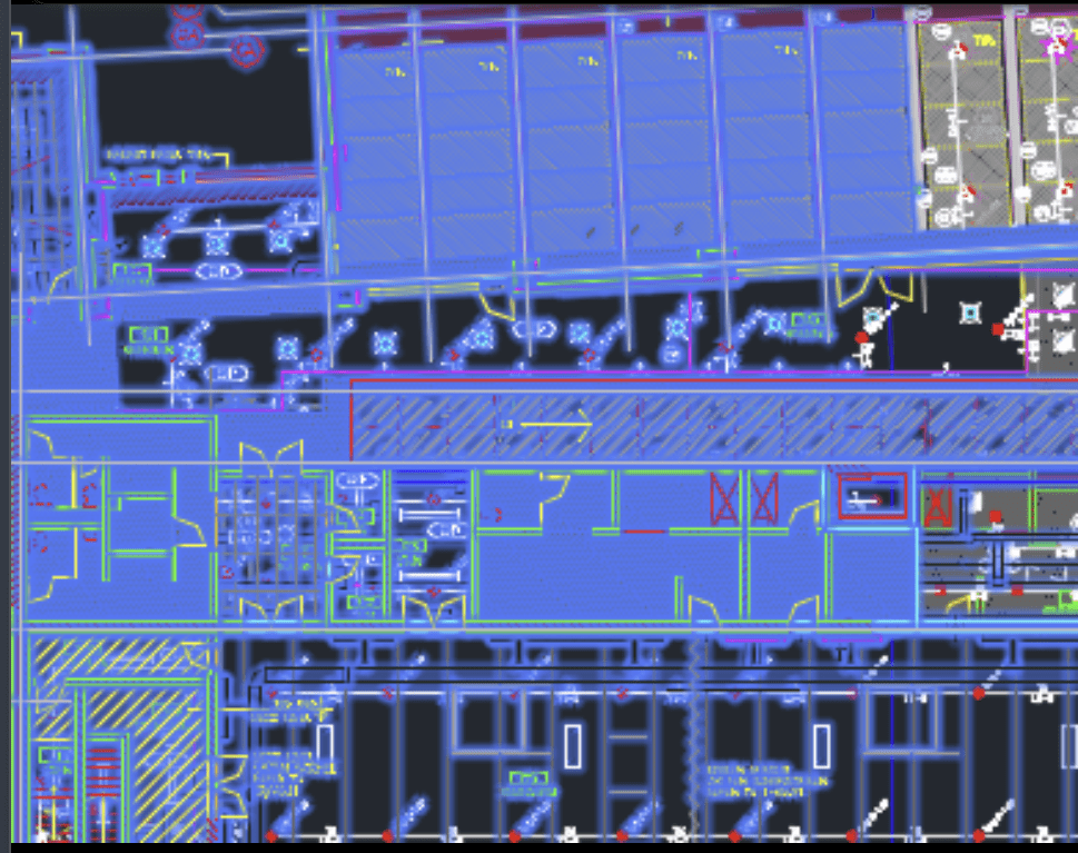
Say you need to select all 1″ riser nipples but don’t want to go through a large drawing looking for and selecting them individually. How to do that? This way:
1. Select all items in the drawing. Alternatively, you could just isolate the riser nipple layer and select those
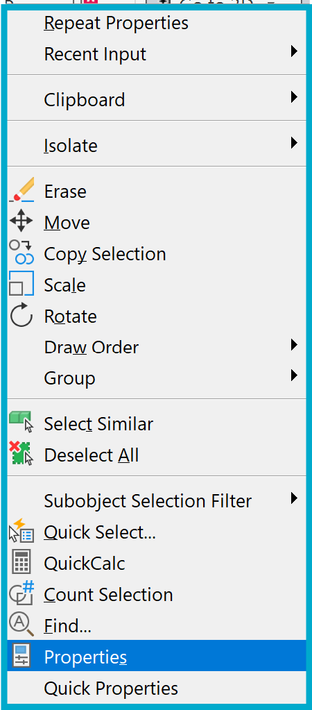
2. Open the Propertiespalette by Right-Clicking and picking Properties or hit CTRL+1
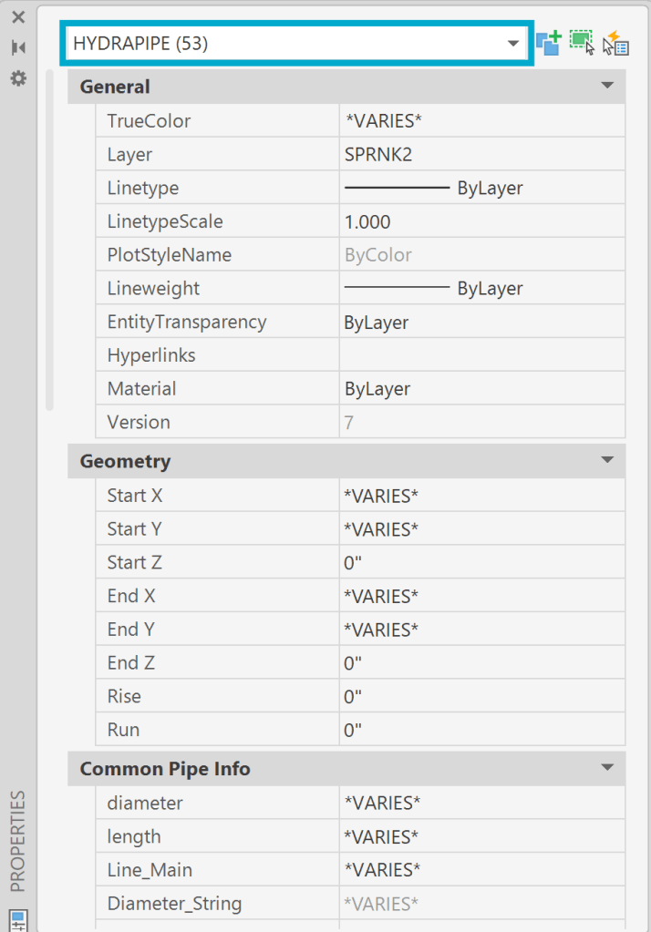
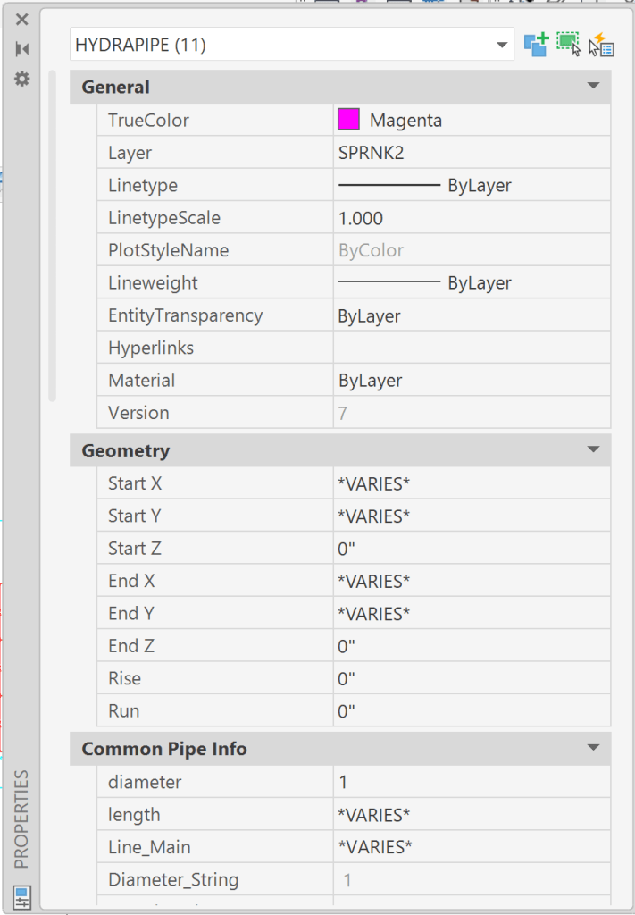
3. Pick the drop down list and pick HYDRAPIPE. This is the internal name of our riser nipples. All other items are now ignored
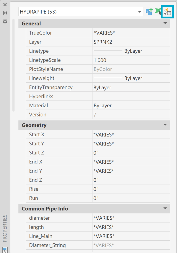
4. Pick the Quick Select button
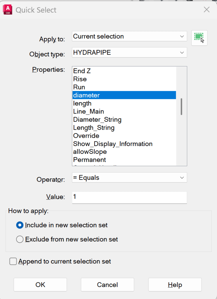
5. Pick HYDRAPIPE under Object type then diameter under Properties, then type in 1 under Value. Make sure Include in new selection set is selected and pick OK
6. You now have a selection set of only 1 inch riser nipples. You can change the diameter, length or whatever at this point
Note: if you use inch marks on your diameters, then you would need to type in 1″ as the Value in Step 5, above.