If you want to use a new type of hanger, or are a fab shop that gets a job from a contractor that uses a hanger type that you do not have, it is easy to add that new hanger type to your own machine. A hanger is an assembly, and an assembly is just…
Recently our previous blog service (Typepad) ended their business – so, we have a new home. It will take a bit to get images back and displaying properly, but we are working on it! Final pageview count of original Typepad blog: 387,232
A customer called today asking how to enter a 1″ black plastic underground pipe for the calc. This particular situation sounded unique enough that I did not tell him to add that pipe type to our database, as I would have if he expected to see this pipe type used repeatedly. I told him to…
Many of our users aren’t aware of the fact they can customize the cover sheet logo in HydraCALC. These steps are pretty easy and can normally be done in about 5 minutes.
1. You’ll need your logo, preferably as a .BMP and with a resolution of 500×500 pixels or greater, but any image type will do.
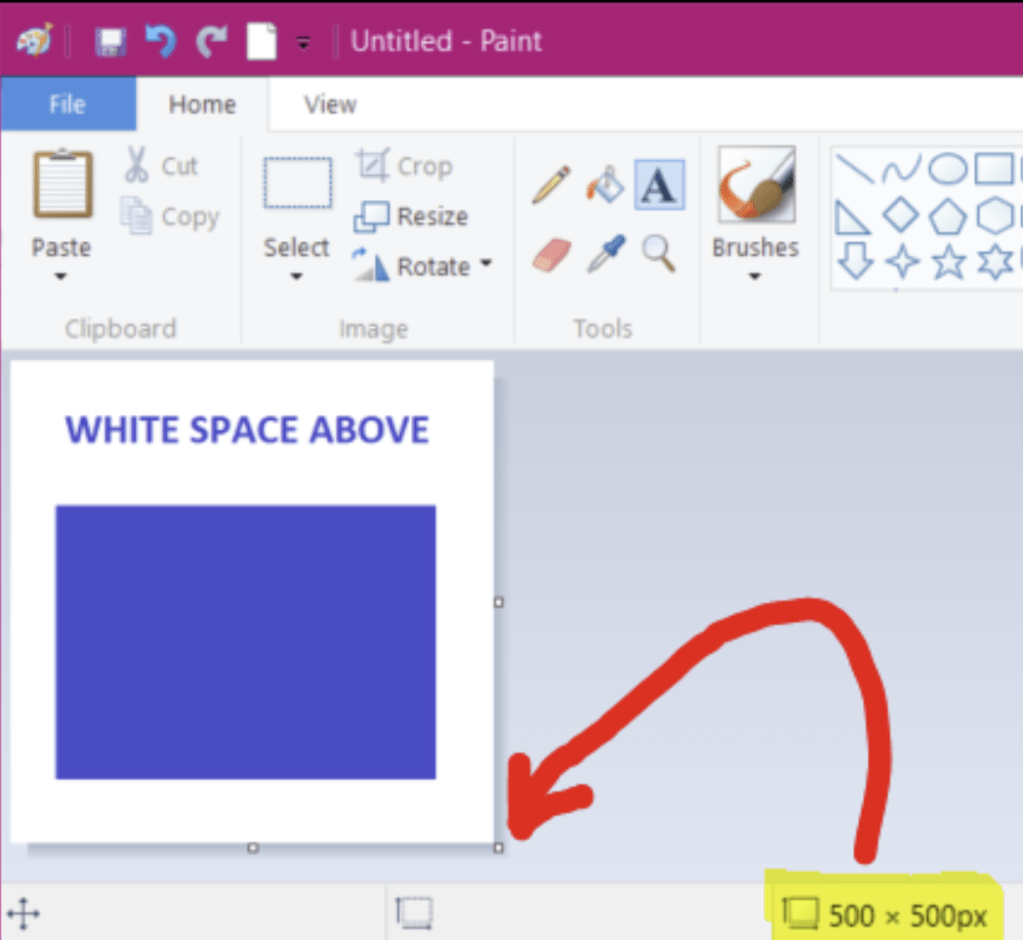
2. Open your image file using Microsoft Paint. Check the pixel size of your canvas; you’re trying to get to as close to a square image as possible. You can click the grips at the edges of your canvas to adjust it as necessary.
3. In the image above, the canvas is exactly 500 x 500 pixels. Make sure to leave some white space near the top, this means your image will be closer to the bottom, not centered inside the canvas.
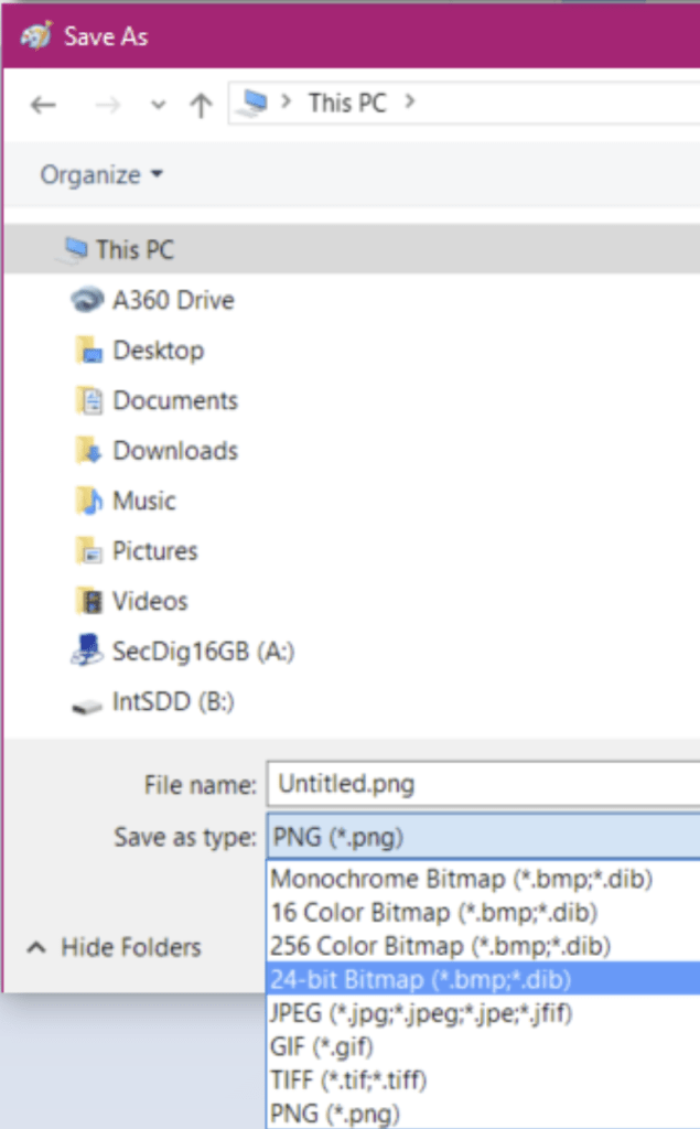
4. When ready, save the image as a .BMP file. When you click ‘Save as…’, select the option 24-bit Bitmap (*.bmp)
Save the file to this folder [local drive]:\HES\HydraCALC\Ver50\Data\Setup\Reports and use the filename yourCompanyName
5. Using Windows File Explorer, browse to the location [local drive]:\HES\HydraCALC\Ver50\Data\Setup\Reports and locate a file called BLANK.DAT. Make a copy of it then rename it to yourCompanyName.DAT
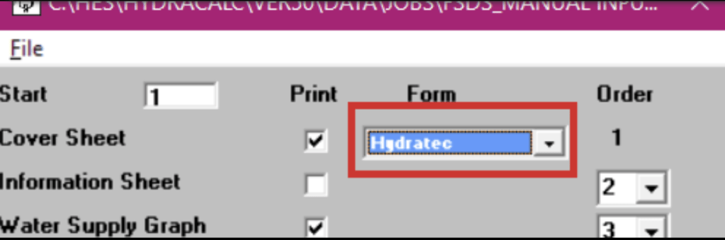
6. You can check your logo by going to HydraCALC, then go to File|Print Final. When HydraVIEW opens, in the Cover Sheet drop down, you’ll see your newly created logo in the list.
7. If you feel some adjustments are necessary, you can click on Tools|Page Setup then adjust the values in the Cover Sheet Graphics area in regards to the Tab, Width & Height. The tab value pushes the image from the left to the right, and your width and height are a ratio of your image’s width and height.
Good luck and get in touch if you need any clarification.
With HydraCAD v56 for AutoCAD 2019 and updates for HydraCAD v54 and v55 due to be released soon, this would be a good time to revisit backing up your workspace. A common reason some of our users decide to hold off on running a HydraCAD update is due to the fact they’ll end up losing their toolbar positions in their AutoCAD work area. This is your ‘workspace’, and with this blog post we’ll cover saving and recovering it. Near the bottom of this post you’ll see steps on sharing workspaces between computers and pulling a workspace from an older AutoCAD into a new AutoCAD.
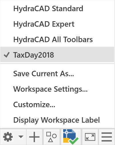
AutoCAD’s Customization Menu, the toolbar along the bottom right of your screen with a LOT of buttons, should have a gear icon, this is for your Workspace Settings. If you cannot see the gear icon, click the hamburger icon at the far right then turn on the Workspace Switching option. You can also turn on the Workspaces toolbar, found in the Acad group of toolbars.
SAVE YOUR WORKSPACE
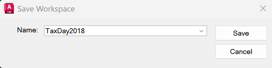
Before anything, we must save your configuration. Select ‘Save Current As…’ from the list (or type in WSSAVE at the command prompt) and type in a name for the workspace. If you’ve already saved one, select it from the list to overwrite it with a new one. Personally, I like to use the current date so I’ll remember the last time I backed up my workspace, but whatever you decide is up to you.
You can confirm it was saved by selecting the list of workspaces as you’ll now see it as an option .
RUN THE UPDATE
At this point you’ll run the HydraCAD update. At its conclusion, you’ll notice your toolbars have realigned themselves to their default locations and your workspace is no longer in the list of saved workspaces.
RECOVER THE WORKSPACE
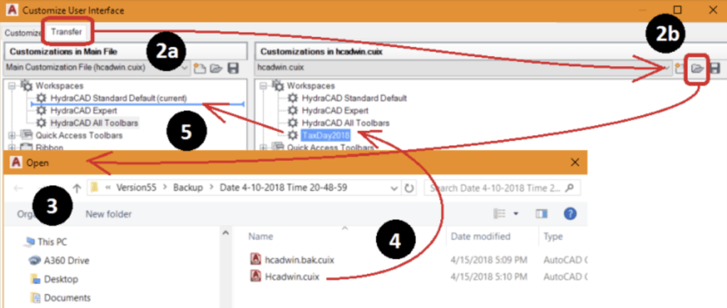
See the image below for help with steps 2 through 5.
1. From the workspace drop-down menu (shown in the image above), Select Customize.
2. In the Customize User Interface window, select the Transfer tab (a), then the Open button (b) on the right side.
3. Depending on your version of AutoCAD/HydraCAD, you will navigate to one of the following folders;
4. You’ll find a sub-folder based on the date and time of when you ran your backup. Double-click it then double-click ‘HCADWIN.CUIX’.
5. On the right pane, you will see your previously saved workspace in the list. Click and drag it from the right to the left pane where it says ‘Workspaces’.
6. Click OK in the Customize User Interface window to return to the drawing and a command prompt. You’ll now see your saved workspace has returned to the list.
SHARING WORKSPACES
You can use this method to copy a workspace from one computer to another; the file you’ll be looking for is HCADWIN.CUIX, use the one found under \HES\HydraCAD\Ver50\Programs\Version5_\ and your least intrusive method is to copy it to the desktop of the new computer and browse to that location when going through the transfer process. Delete the file from your desktop when complete.
INSTALLING A NEW VERSION OF AUTOCAD
This method should work fine between versions of AutoCAD as well (as long as the AutoCADs don’t have too many years between them). When installing a new AutoCAD, always remember to NOT migrate your settings over. When the Acad and Hcad installs are complete, you’ll use the steps above to transfer your older version Acad workspace over to your newer version Acad workspaces.
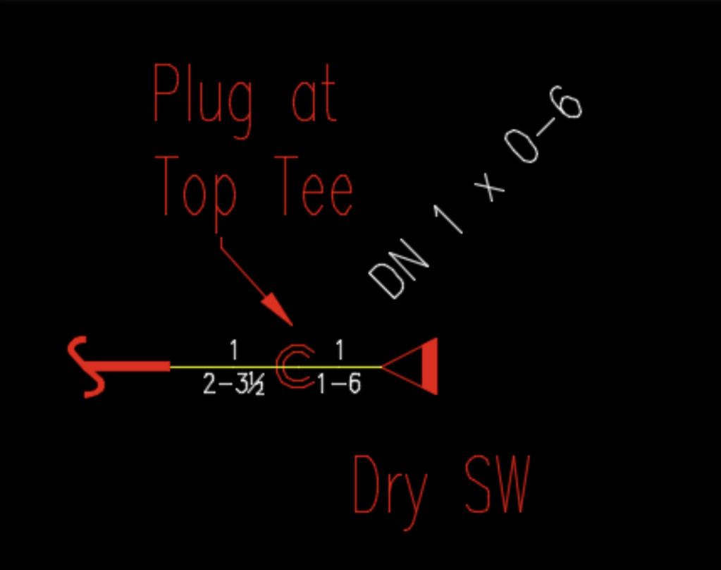
From a customer: Can I AutoList a plug at top of this tee?
From my co-worker Bill – yes you can:
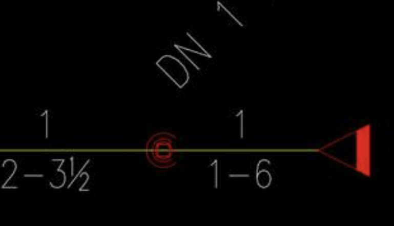
This will list the correct tee at the end of the riser nipple and will list the plug with the miscellaneous material.
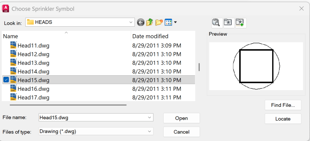
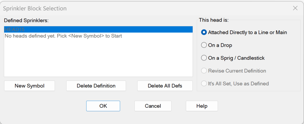
1. Set up a sprinkler to use for this purpose. We often use Head15 because of the way it looks
Define the sprinkler head as Attached Directly to a Line or Main
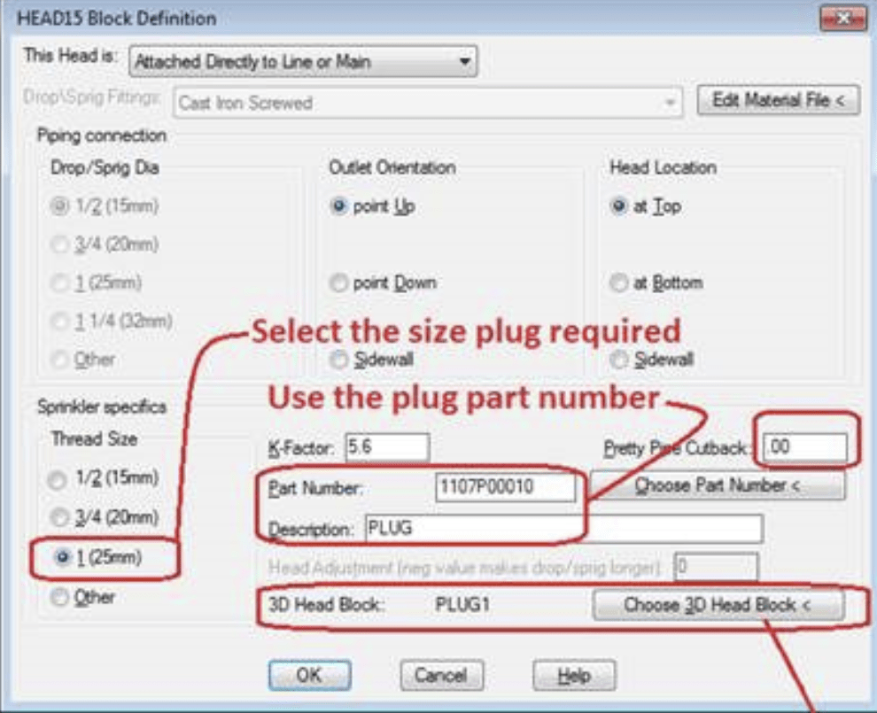
3a. Define the Plug ‘sprinkler’ as “point Down” and “at Bottom” if the plug is at the bottom of the riser nipple. Note: use at Bottom – if the 1’-6” long pipe is lower than the 2’-3 ½” pipe in our example
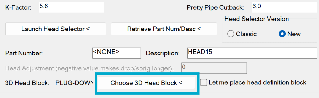
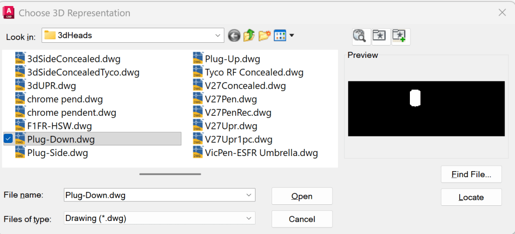
3b. Select Choose 3D Head Block and select Plug1 as the 3D representation
4. Scale the plug/sprinkler block down a bit so you can tell it is there, but not so large as a sprinkler block
My co-worker Paul produced this blurb, on request from a customer who was attempting a Velocity Pressure calculation (a velocity pressure calculation is required by NFPA when designing Fixed Spray deluge systems). This type of calculation requires the use of the Input Types field, discussed in this post a ways back: Why Use Input Types?
For this kind of calc, The program needs to know which pipes are perpendicular at pipe intersections. The perpendicular pipe is where the velocity pressure is used to determine the flow into the pipe.
You can use any of the default Input Types from in the selection box, in this example we have used the Letters A B & C as the Input Types for clarity
All of the pipe where the flow goes straight through must have the same Input Type. Outlet pipes where the flow is determined by the velocity pressure must have a different Input Type.
In addition to the perpendicular pipe outlets the velocity pressure is also used to determine the flow at a K-Factor where a sprinkler head is directly connected to a pipe. (The sprinkler is the perpendicular outlet).
We used A for the Input Type from the remote sprinkler back to the supply point. We used Input Type B for the pipe that comes off perpendicular to the Input Type A pipes and Input type C for the pipe that comes off perpendicular to the Input Type B pipes.
Based on this, the program knows where all the perpendicular pipe locations are and can calculate the velocity pressures correctly.
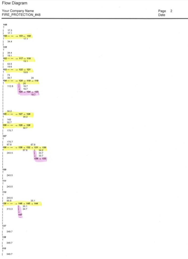
Below is a flow diagram showing all of the B Input Type Pipe Marked in Yellow and all of the C input Type Pipe Marked in Pink. The pipe not highlighted is Input Type A pipe.
The Velocity calculation is performed at the intersection of the different Input Types and the K-factor location.
This link will get you the example job used for this post. We suggest you place it in your \HES\HydraCALC\Ver50\Data\Jobs\Example Jobs folder. Velocity Pressure.WXF
Q: I would like the head guide to have an option to spot the head based on the last one (with Ortho on so they line up). Kind of like the insert multiple sprinklers command. Or add the option to the “insert multiple” where you can access the head guide. I am using the custom guide to layout heads in an attic and am having a hard time getting them to line up.
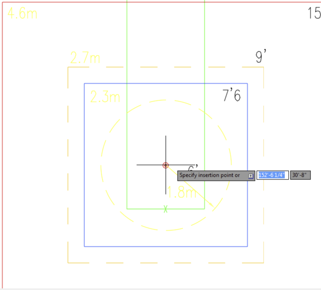
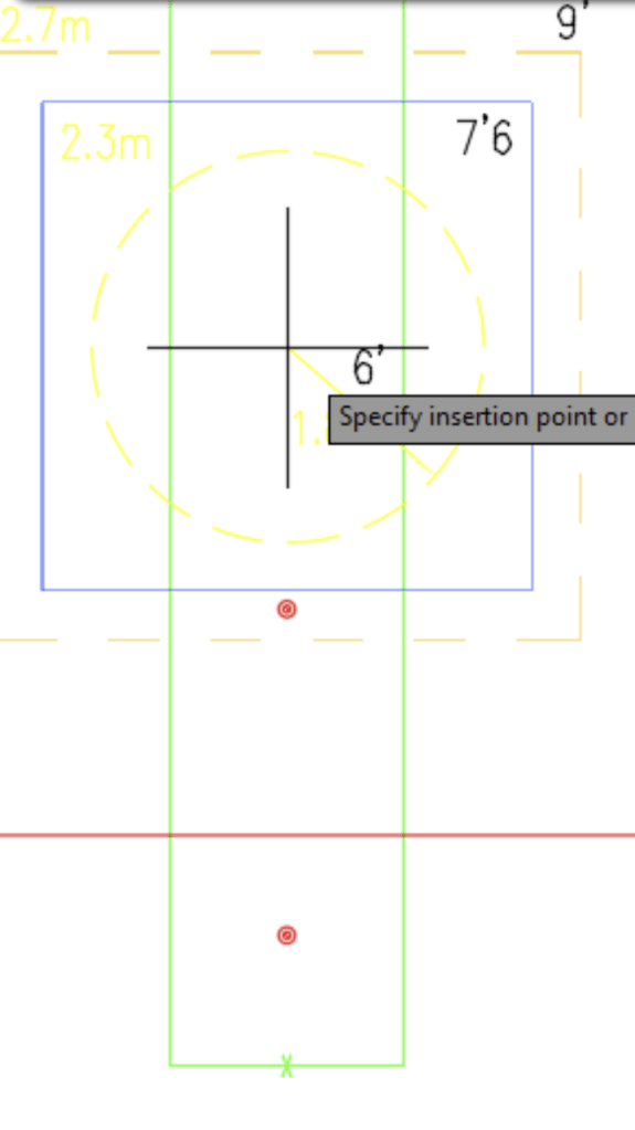
A: This one took me a little bit to figure out. Changing the program for Head Guide is problematic, since we are taking advantage of a specific feature available inside AutoCAD – one that I won’t bore you with, but is not used very often by drafters, if ever. Because if the way it works, we can’t just make it do other things while running it. There is, however, another way to achieve what this custom wants as a result. And that means activating a command before running Head Guide. That command is SNAP (not, OSNAP). Setting the SNAP point will make the cross-hairs move in an Ortho-like motion. We already have a command to automate this – Align Crosshairs with Ceiling.
This is the room. We can use a head guide to run a line of heads up the middle:
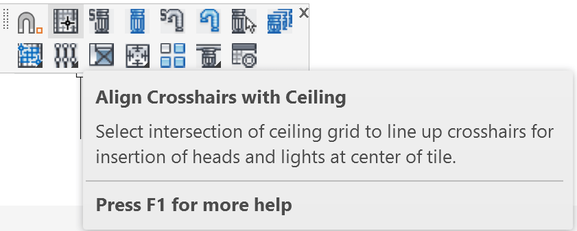
Pick Align Crosshairs with Ceiling on the Sprinkler Toolbar.
Picking this will ask you to select a base point. Select a corner of the room, or even the midpoint of the lower leg
The cross-hairs will now jump in 1 foot increments as you move them. This will work, but it may be a little too ‘jiggly’ for some. To change the SNAP increment, type in SNAP at the command prompt and type in the desired increment. 2′ would probably be best for most situations. But, if you have specific spacing requirements, you could set it to that. A reminder – SNAP can be toggled on and off with the F9 key.
Pick on one of the Head Guide commands. i am using the first one, the Standard guide.
Now, hover the Head Guide over the insertion point of the first head. Then, left click and insert the head.
Next, move the cross-hairs up to the next insert point and left click again, until you have your heads spotted.
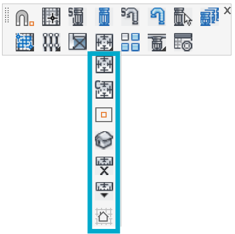
Remember, hit F9 to turn off SNAP or pick Align Crosshairs with Ceiling again. That will turn off SNAP before prompting you to pick another insertion point to align.
A customer from Sweden asked the following this week:
“I have a question about HydraCALC, is there a way to change the default path for where the program initially finds its projects to open?
For instance, now when I press OPEN, it always open “C:\HES\HydraCALC\Ver50\Data\Jobs”, we have our projects in a different location, so for me it would be nice if I could change the default location into our project folder.”
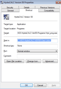
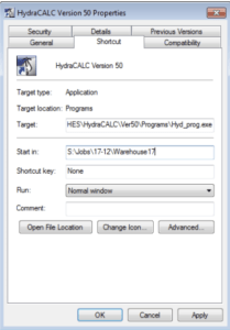
The way to do this is through the desktop shortcut for HydraCALC. Right-click on the shortcut and pick Copy. Then right-click somewhere on your desktop and pick Paste. This will give you a second shortcut to work with, while preserving the original one,
Right-click on the shortcut and pick Properties. Then, pick the Shortcut Tab. Notice the Start in: field. That tells HydraCALC where to look for Jobs when you open or save one.
Change the Start in: field to be the location you want. Pick OK
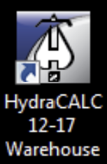
Right-click again on the shortcut and pick Rename. Give the shortcut an appropriate name, so you can find it next time.
You can make as many shortcuts as you like, setting each one to a different job location.
HydraLIST and HydraCAD follow the same instructions.
Want to make your own symbols? Easy Want to use the same symbol for two different temperature heads? Easy
The answers all come down to the same thing. The second one albeit a little differently. And…a trick concerning the word ‘same’
The answer is to start with an existing HydraCAD head, making changes to it (or not) and saving it.
HydraCAD heads are stored in the \HES\HydraCAD\Ver50\Programs\heads folder by default. (you can specify a central location as well per this post: Specify a Central Location for Sprinkler Heads)
To make a new symbol follow these easy steps
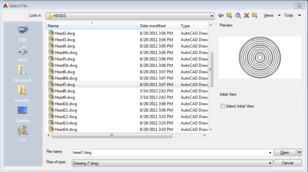
Open the head drawing most similar to the one you want (ie HEAD1, HEAD2, HEAD15)
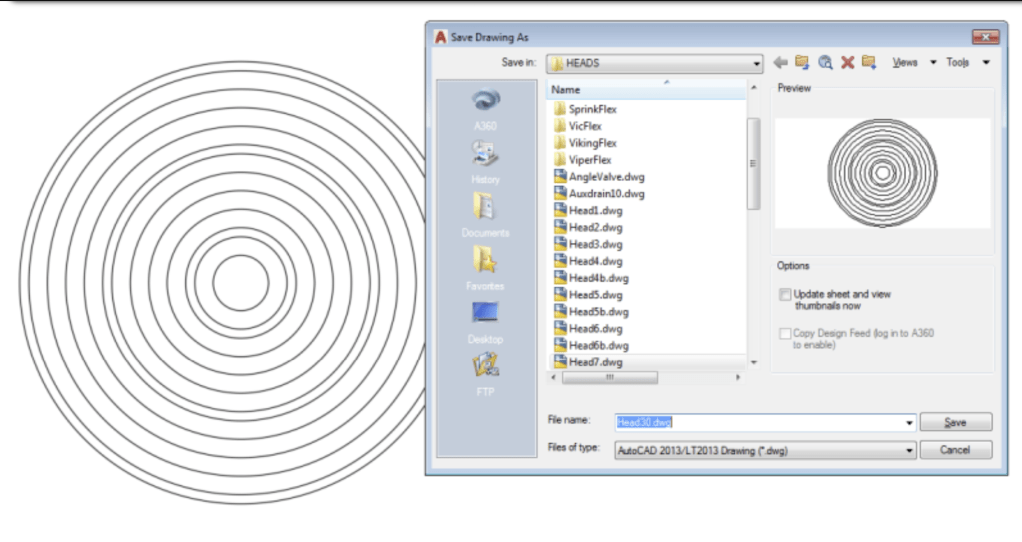
Using SaveAs, give the drawing a new name
Change the symbol as desired and save it
Example – Making a new head symbol
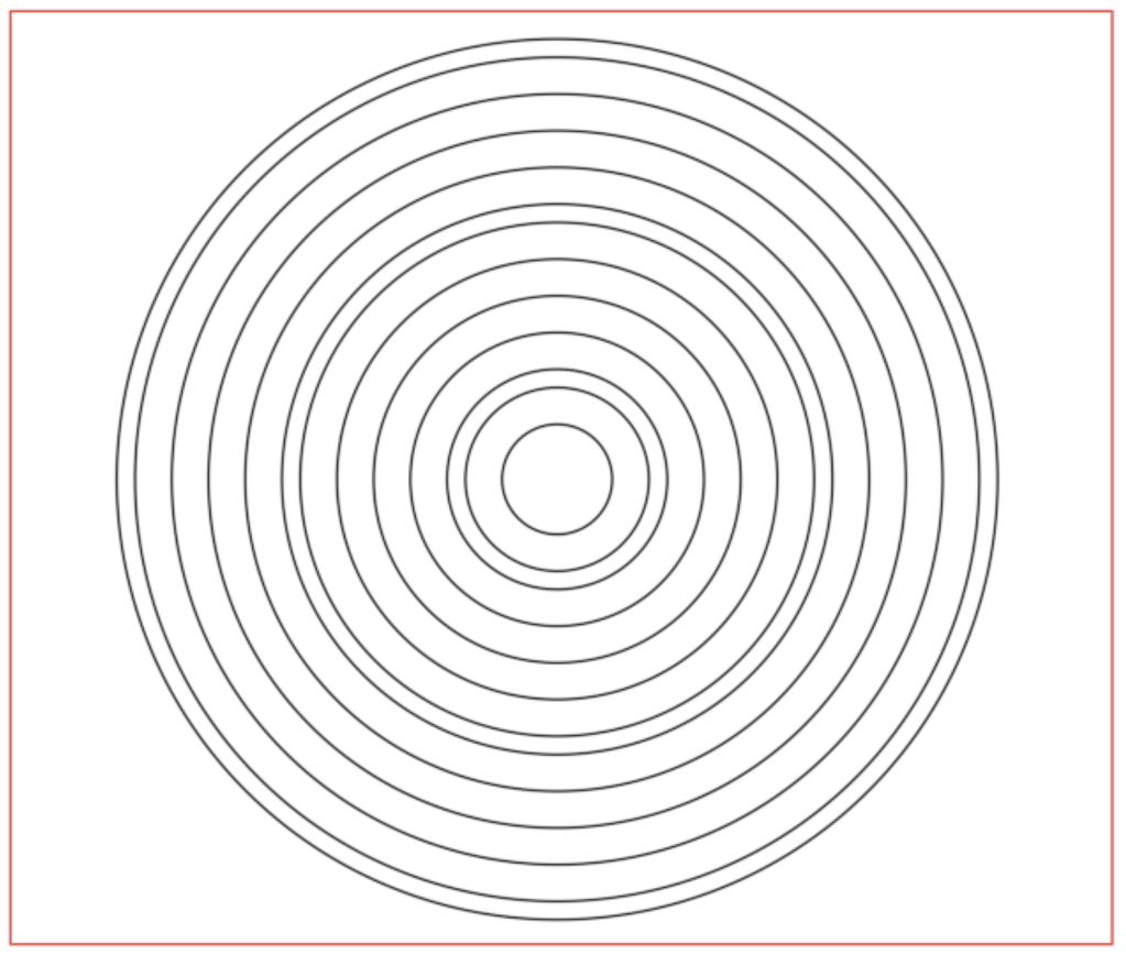
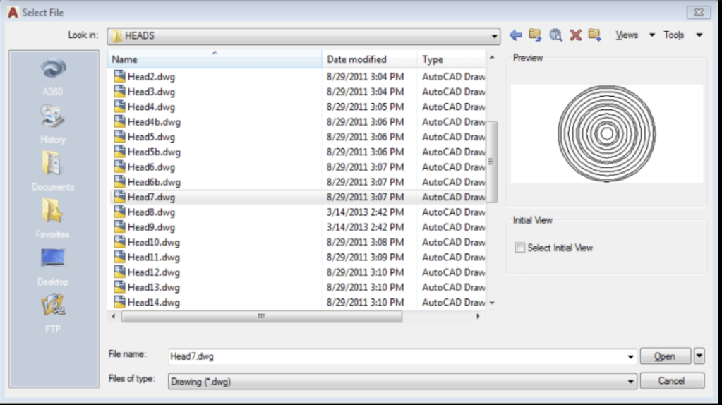
1. Open HEAD7
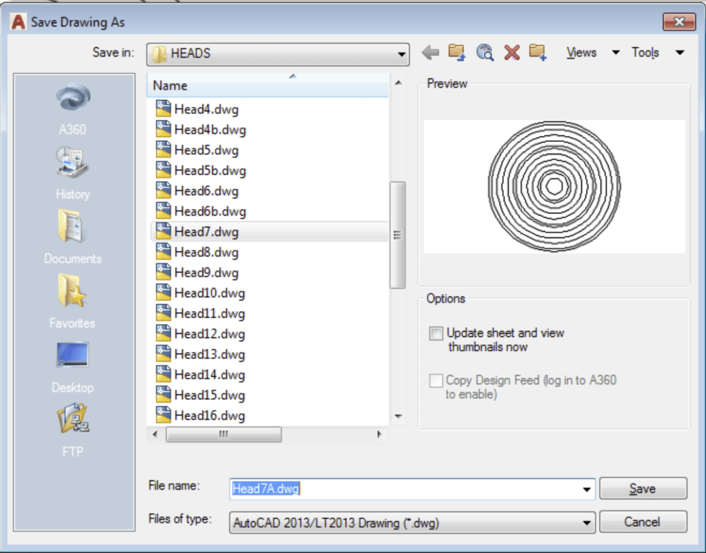
2. Immediately SaveAs HEAD30 (immediately, so that you don’t save over the original!)
3. Make Changes to head, as desired and Save it
The ‘trick’ concerning wanting to use the same symbol for two like heads, but of different temperatures is as follows:
Example – Using the same symbol for two different temperature heads
1. Open HEAD7
2. Immediately SaveAs HEAD7A
That’s it! When you are defining sprinkler heads, just define one as 165º and the other as 212º (or whatever)
Q: Over the past few years we have added several items to our database and many of the items require a long description. I have tried to abbreviate as much as I can but I am unable to get the description small enough to fit in the “Item” description box in HydraLIST. Is there any way of getting this to be more than 30 characters long. Thanks for all you help.
A: From co-worker Paul McKenna – We have had a long description in HydraLIST for some time now although most people do not use them
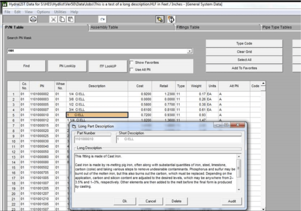
You must be in the General Data section where you alter the data associated with HydraLIST. In there, pick P/N Table
The items that have long descriptions will have the description highlighted in orange.
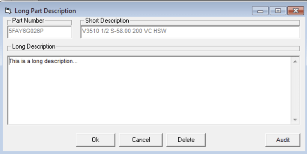
The long description is accessed by right clicking on the fitting description.
Enter the long description and pick OK to save the description. Pick cancel to return to the P/N Table without saving. Pick Delete to remove the long description and return to the P/N table. Pick Audit to eliminate long descriptions that are in the long description file but have not entries in the P/N table. Long descriptions can be added to the database when picking sprinklers for the Head Selector or Valves for the Valve selector by answering ‘Yes’ when prompted when collecting data.
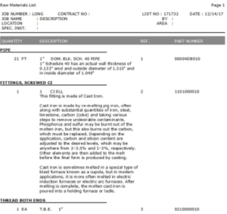
Long Descriptions are included in the data when exporting or importing data in the P/N table. You will see the Long Description when you print out the Raw Materials List
A customer asked last week: How do I properly use a 4×3 Bell Reducer so that it lists correctly?
The answer, according to my co-worker Bill McKenna:
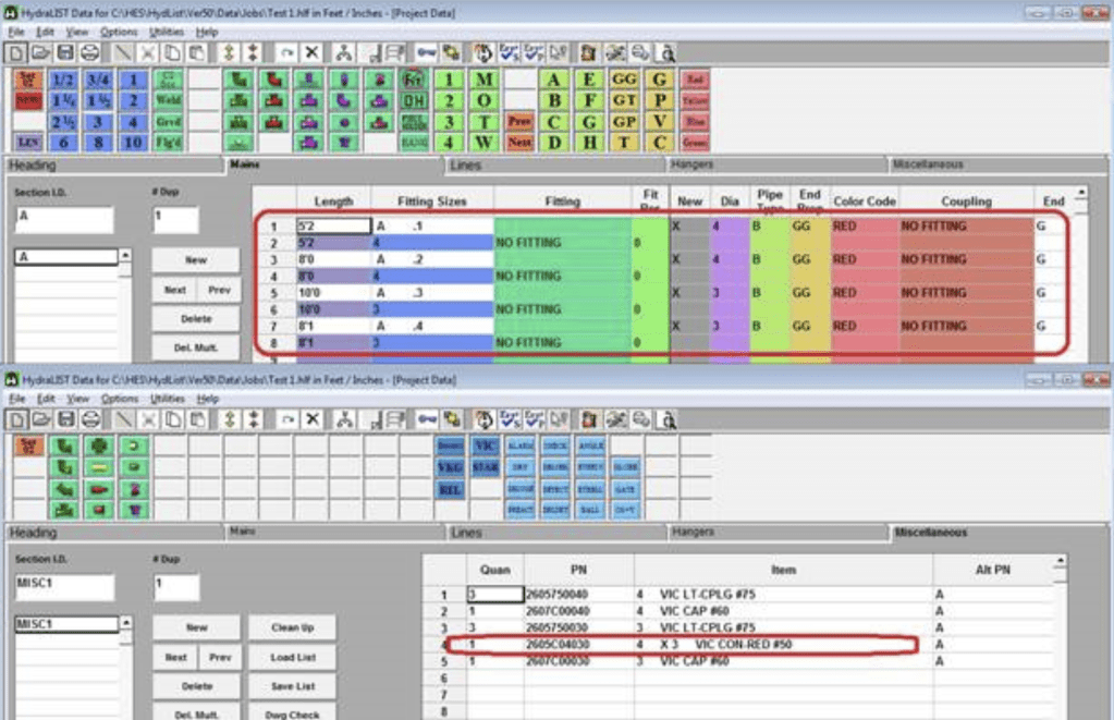
1. A coupling should already be on the pipe intersection where the diameters are changing
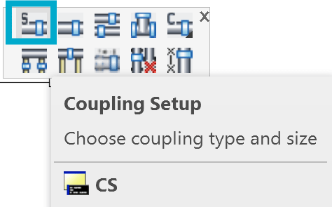
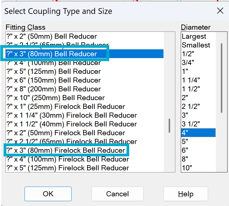
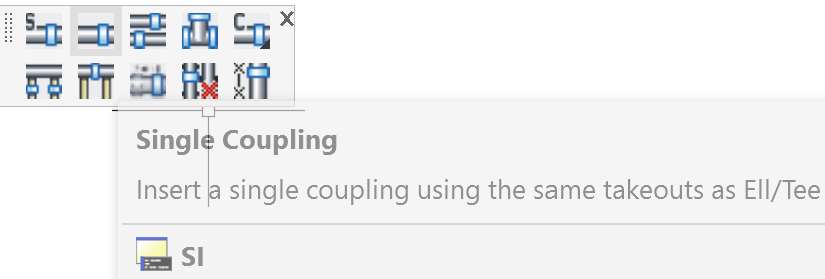
2. Select the coupling type required for the Bell Reducer being used:
The Diameter selected at right will fill in the ? mark – IE picking 4″ will complete the 4 x 3 Reducers
3. Use Single Coupling to insert the Bell Reducer
Select the SMALLER diameter pipe for the insert. A coupling should already be on the pipe intersection where the diameters are changing. The command will break the pipe selected and add a block representing the reducer and a coupling.
Result: An OVERRIDE block will also be inserted. The 0′-3″ long pipe inside the reducer will not be included in the stocklist created by AutoList. Note: The diameter found in the reducer should be the larger of the two sizes. The point of the reducer should always be towards the smaller diameter pipe.
I have a quick question. How to I list 001 Victaulic 90’s and 009 Victaulic Couplings? Is there an equivalent? I cannot seem to locate them in HydraLIST
The answer depends on which program is being used:
Using AutoList from HydraCAD:
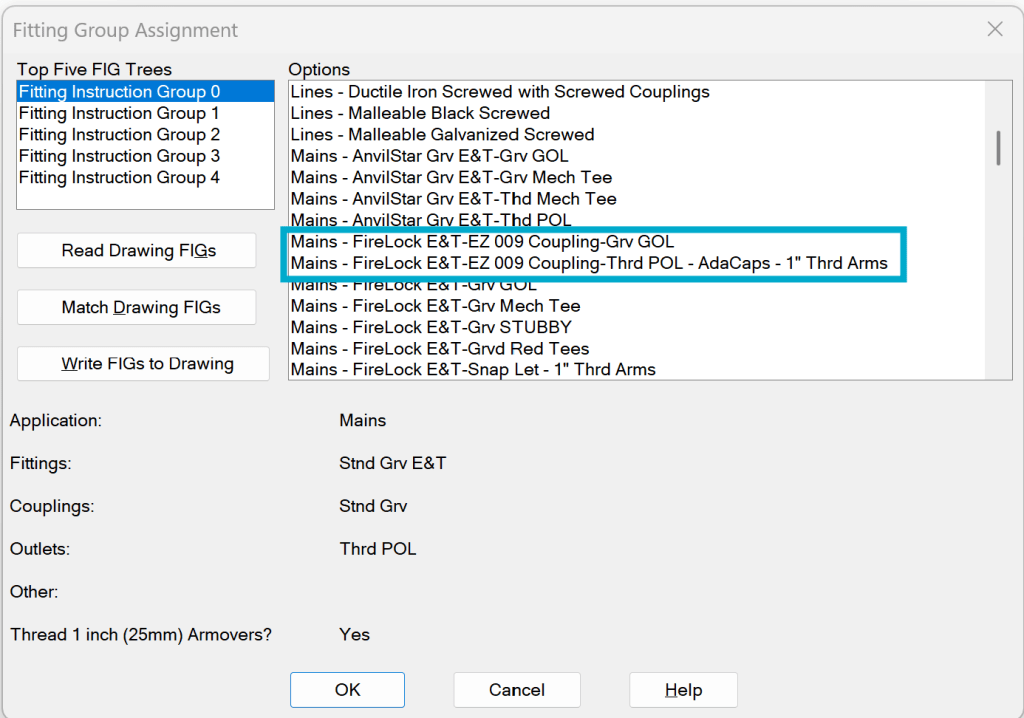
Change your fitting mapping to one of the available Firelock Fitting with 009 Coupling Groups – that’s all it takes
In HydraLIST:
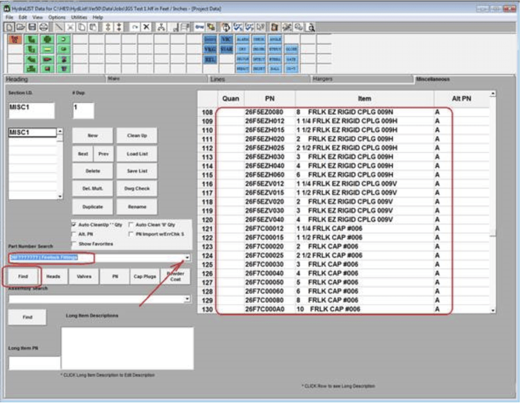
All of the part numbers for these fittings are included in the standard part number database.
In the MISC Input – key in 009 or 26F Firelock Fittings into the Search field and pick FIND to display all the fittings. Enter quantities and select Clean Up when done to remove those items that are not quantified







 The H-Factor