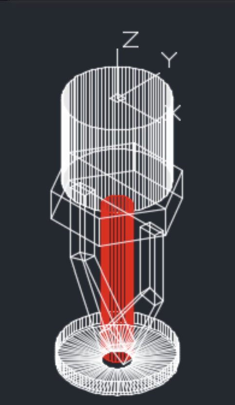
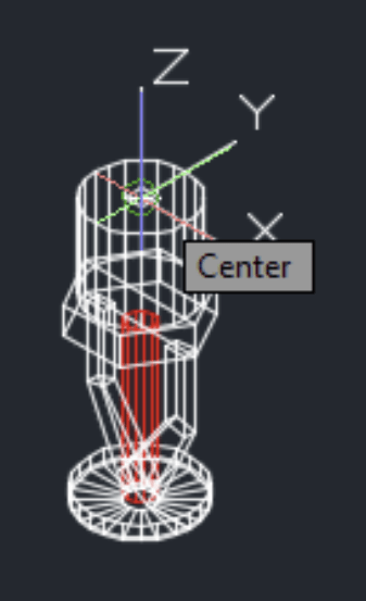
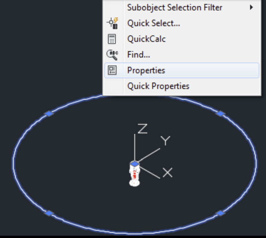
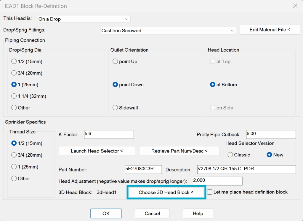
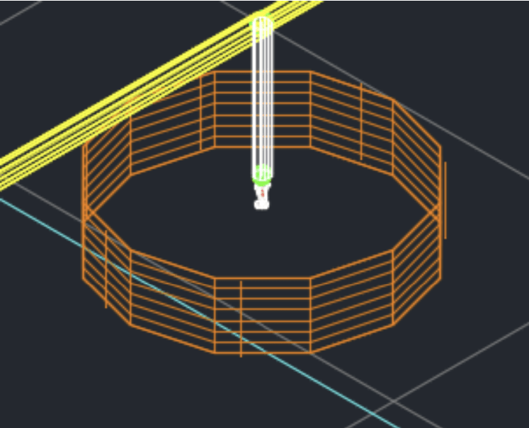
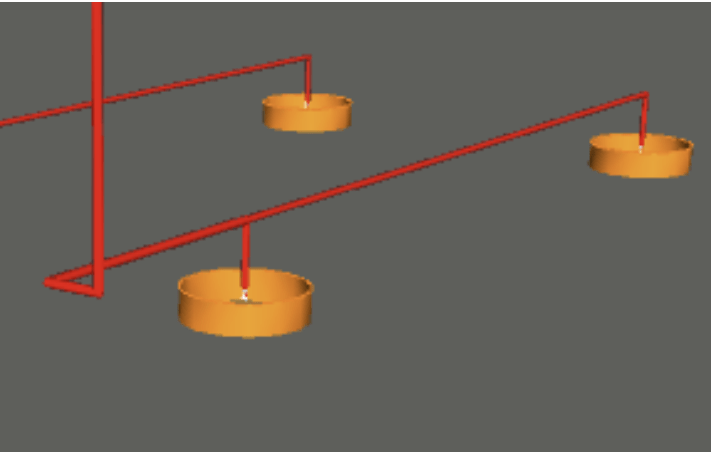
If you want to use a new type of hanger, or are a fab shop that gets a job from a contractor that uses a hanger type that you do not have, it is easy to add that new hanger type to your own machine. A hanger is an assembly, and an assembly is just…
Recently our previous blog service (Typepad) ended their business – so, we have a new home. It will take a bit to get images back and displaying properly, but we are working on it! Final pageview count of original Typepad blog: 387,232
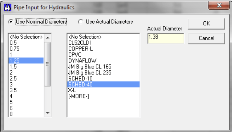
A customer called today asking how to enter a 1″ black plastic underground pipe for the calc. This particular situation sounded unique enough that I did not tell him to add that pipe type to our database, as I would have if he expected to see this pipe type used repeatedly. I told him to…
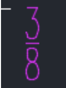
A customer we were training recently wanted to know how to create 3/8 and 5/8 fractions for use in hanger details. The wanted to know if we have those in our fonts. We do not. However, AutoCAD can automatically generate those, and any other fraction you can dream up, using the MTEXT command (not TEXT).
If you start the TEXT command, and enter 3/8, that is just what you will get:
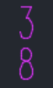
But, if you start the MTEXT command and type in 3/8, this happens automatically:
Start the MTEXT command and type in 3#8 (instead of 3/8). This will produce the following:
But what if you want a diagonal fraction, not a horizontal one? There is a way to do that, too!
You can even create them without the slash at all. Type in 3^8 and you will get:
If you want to make the formatting permanent, AutoCAD has something for that as well.
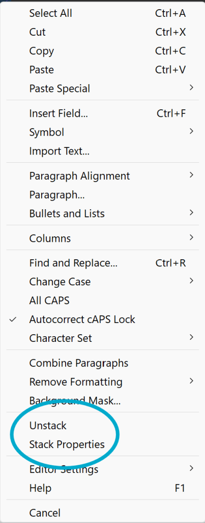
Highlight the stacked fraction within the MTEXT – You can double click the text to be put into edit mode. Then, select the fraction and right click or double click. Pick the Stack Properties menu item.
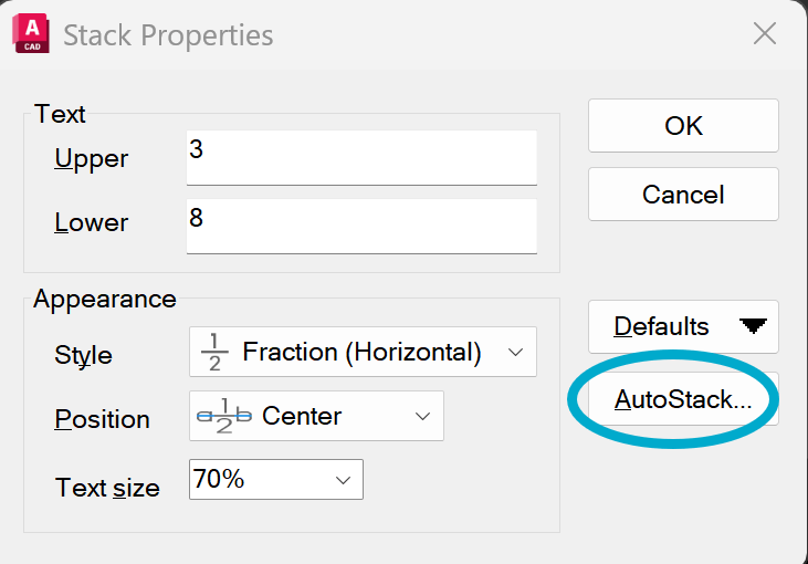
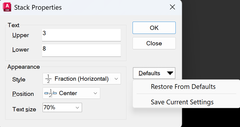
This will give you access to the Stack Properties dialog box, where there are more options than you probably ever wanted to know about:
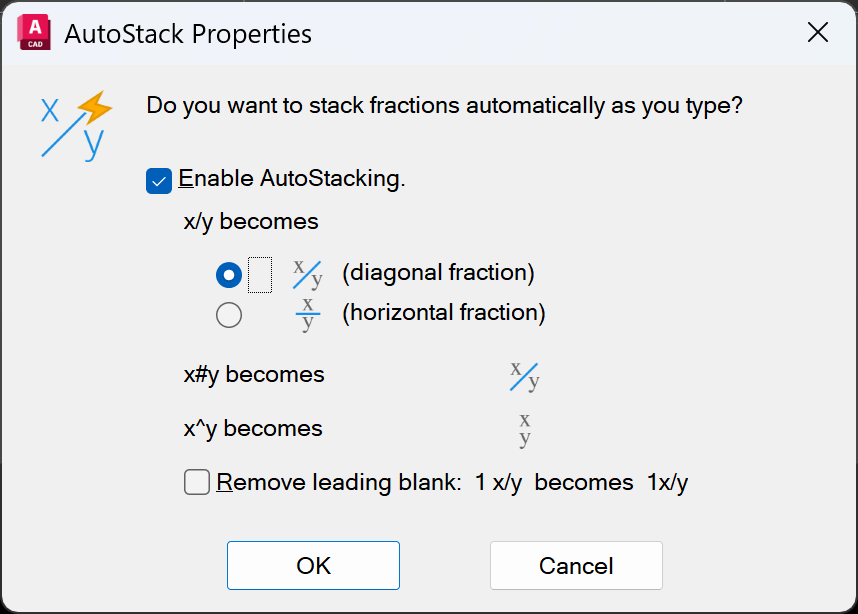
If you pick the AutoStack button, you will be able to change the default behavior to a diagonal slash, among other things
Pick OK when done, set other things how you like them, pick Defaults and Save Current Settings.
FYI – You can start the MTEXT command either typing MT in or using the MTEXT button on our HydraCAD Utility toolbar
Hanging from bottom of steel is not as prevalent as it used to be, but it is still done often enough. A change was made recently to HydraCAD to allow quicker use of the Steel Depth blocks added to steel (or any material) structures. If these steel depth blocks are inserted, the program can now reference them more easily.
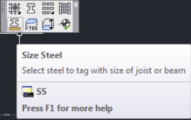
First, you will need these blocks inserted. To do that, use the Size Steel (SS) command from the Steel toolbar:
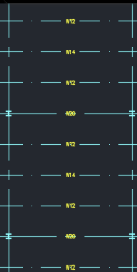
Select the steel members to be sized. Again, keep in mind you can insert these on concrete or timber members as well
After you draw the pipe and label building elevations, you are ready to add the hangers.
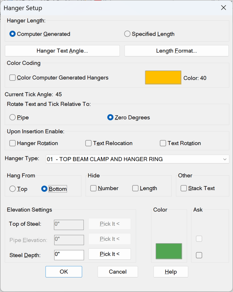
The one important item of note in the Hanger Setup dialog box is the checking of the Bottom option in the Hang From section (above). This must be checked to use the Steel Depth blocks.
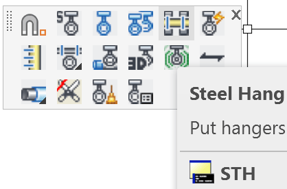
Next, use the Steel Hang (STH) command to insert the hangers:
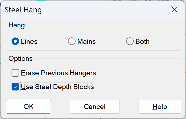
Check the Use Steel Depth Blocks option:
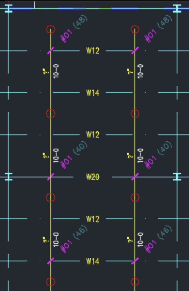
When you pick the steel members to be hung to, the steel depth will be read from the block attached to that steel and subtracted from the rod length. If there is no steel depth block, no hangers will be inserted.
Occasionally we get contacted by a customer who states that something is wrong with his drawings, but when they are opened on another computer, they are fine. If one of the usual suspects is not to blame, we then compare the AutoCAD settings on the ‘bad’ computer to a ‘good’ computer.
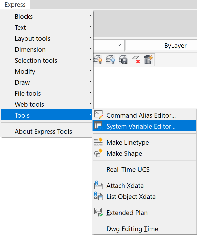
AutoCAD includes an Express Tool to help with this – System Variable Editor (SYSVDLG)
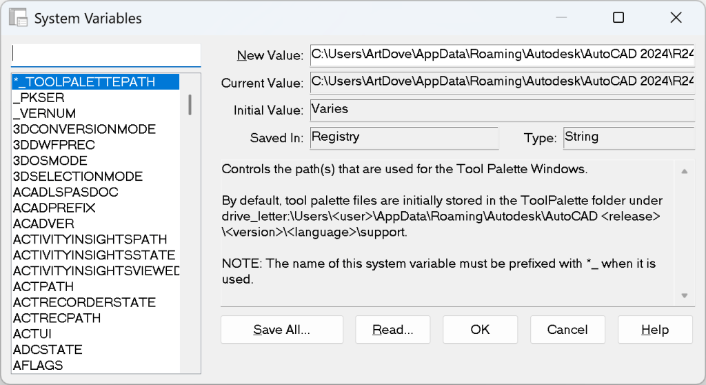
If you start the command, it will bring up the Sys Var Editor:
This utility will allow you to see every variable setting, with an explanation of that setting. You could, in theory, have both computers side by side and then scroll through each setting, but there is an easier way.
Pick the Save All button and enter a file name of something like badcomp.svf. This will export all the settings. You can then do the same on the good computer and name it goodcomp.svf. These files can be opened in Notepad and compared side by side. We use a free utility called FCompare to find differences in any two files.
Please note that the vast majority of differences between any two computers are irrelevant. These include things such as last command used and coordinates for insertion. Ignore these. Instead, focus on differences pertaining to the issue you are trying to diagnose, and change those settings one by one until you figure it out.
HydraCAD has a tool to generate a hanger point file to be loaded into a total station, and that file can include seismic brace locations as well.
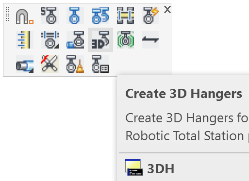
The command is located within the Create 3D Hangers command, found on the Hangers toolbar:
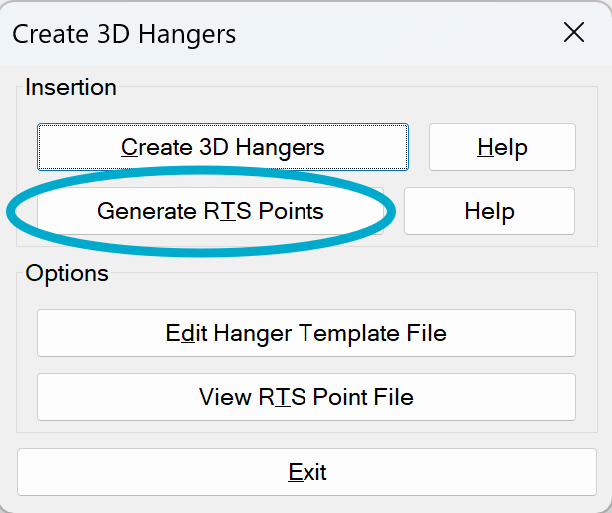
Pick the Create 3D Hangers button to get to the Generate RTS Points command.
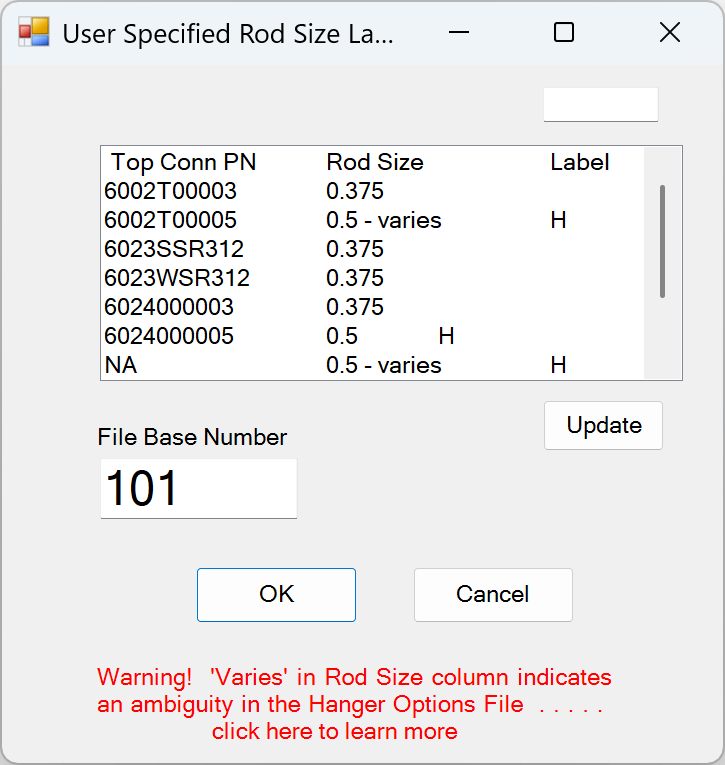
This will produce a report dialog where you can enter the start number for the PTS point. Use the Help button for exact details.
Example Drawing
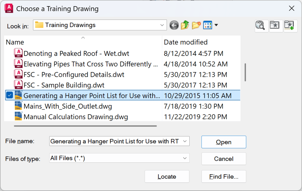
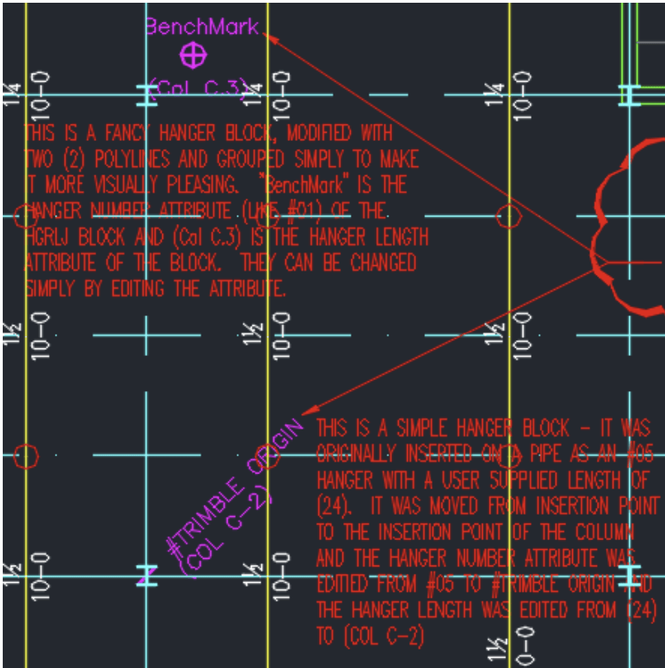
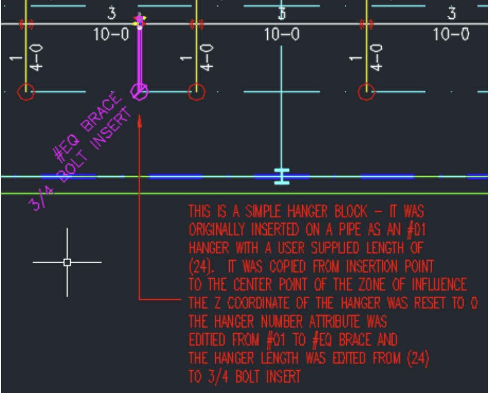
HydraCAD includes an example drawing showing some special considerations that must be made when generating the file. These include two ways of embedding the Origin Point for the Trimble and a way to denote seismic braces so their insertion points are also recorded. This drawing can be found in the HydraTools pulldown menu->Tools->Training Drawings, or type in TD. The drawing name is ‘Generating a Hanger Point List for Use with Trimble Stations.dwg’.
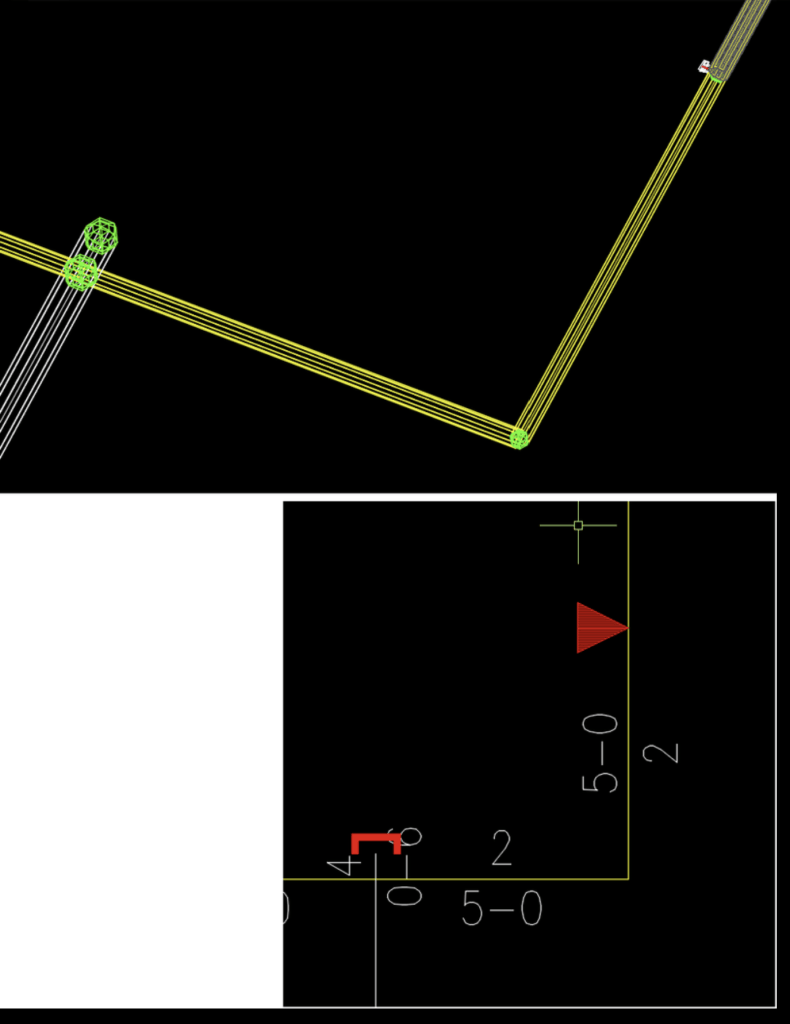
If you’ve run into the problem where after returning your drawing from 3D to 2D you notice some sidewalls are being flipped, we can explain.
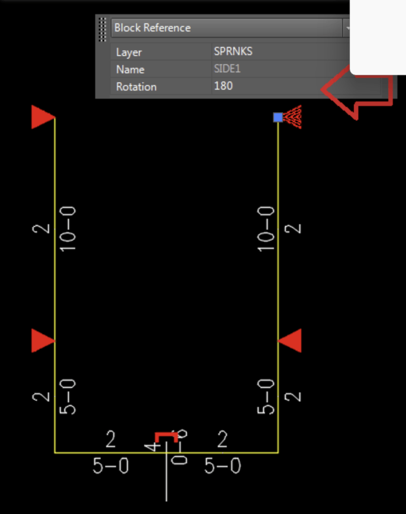
This is a result of how AutoCAD handles mirrored blocks. In the the image below, the two sidewalls on the left side have been inserted using HydraCAD’s sprinkler insertion tools. Their insertion angle is 180⁰, which is correct.
The two on the right side have been mirrored and although they are displayed graphically correct, the Insertion Angle property still shows 180⁰ where it SHOULD be 0⁰.
When raised to 3D and returned to 2D, you’ll notice the sprinkler head will be displayed in the Rotation Angle property (180⁰) and it appears HydraCAD flipped the sidewalls.
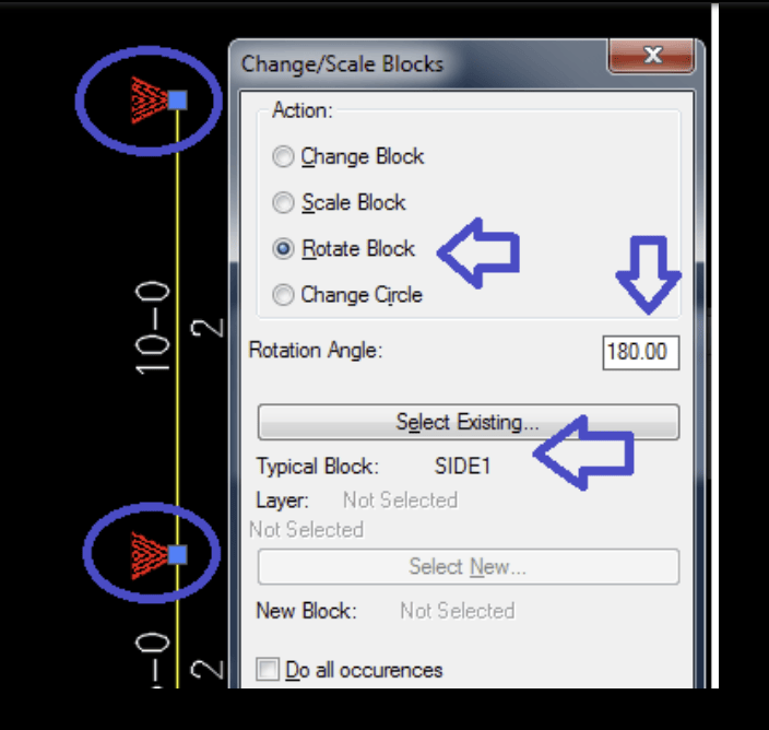
The two solutions are to either erase and re-insert the sprinkler heads at the proper angle or to use the CHB command to rotate multiple sidewalls to their proper direction (at the same time). The command can also be found under the menu HydraTools|Modify|Blocks|Change/Scale/Rotate Blocks.
After rotation, you may find the pipe diameter and length are on the opposite sides of the pipe than expected. It is easiest to erase these and resize the pipes, or you can use grips to move them where needed.
Many larger sprinkler companies and fabricators modify their HydraLIST data – part numbers, prices, assemblies, pipe types, etc. It can get really tiresome to copy the HydraLIST data files to each users’ machine whenever data is changed. Enter the Master Data Location. To set this location to a common folder is really simple. Here are the steps:
1. Copy the contents of the master computers \HES\Hydlist\Ver50\Data\Setup folder to a common location, such as a network drive. Copy all the files the first time. After future updates, the master only need copy files whose dates are newer than the common folder file dates.
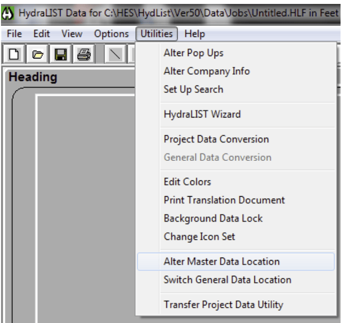
2. In HydraLIST, pick the Utilities pull down menu, then pick Alter Master Data Location (below)
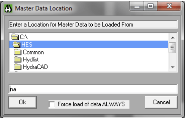
3. This will bring up a folder selection tool. Pick the common folder you created.
When a remote HydraLIST client opens the program, it will check the specified path above to see if any of the remote files are newer. If they are, they will be automatically copied to the client workstation. Check the box for Force Load of Data Always if you want the system to overwrite the files regardless of the date.
HydraCAD’s templates have layers built into them, as you are already aware. These templates specify properties of the layers such as color, linetypes, plot status, and line-weights, among other things.
Many users are content with using the layer properties we have set as defaults, but what if they want to change them? What if they change their templates, but the HydraCAD settings keep coming back after Super Purge or Rebuild HydraCAD Layers are used?
I want to start this conversation by explaining that there are two things that control the layer settings in a HydraCAD drawing – the template used and the Layer Script (LAYER.SCR) file.
The Template
The template is already understood by most as the drawing which initially sets the layer properties when a new drawing is created. Most users use the Layer Manager to set and change the properties they want, and to add new layers as needed.
The Layer Script
What is this? A script file is a type of AutoCAD file that runs a series of AutoCAD commands, such as those used by the -LAYER command. If you type in -Layer at the AutoCAD prompt (as opposed to Layer, which brings up the Layer Manager), you will see the options available when defining layers. These options can be automatically filled by a script file, which is that the LAYER.SCR file does. This file is run whenever you use the Super Purge (PUR) command or the Rebuild HydraCAD Layers (RBL) command from the HydraTools->Tools menu or typed in.
Note: The script is run by the Super Purge command because the AutoCAD Purge command (which is part of Super Purge) purges out all unused HydraCAD layers, and we need them there.
The commands I will now explain are all found on the HydraTools->Options menu.
Editing the Layer Script
We rather you didn’t. Really. There is a problem inherent in editing this type of file and things can get messed up in a hurry. There is a better way, which I will get to in a moment. But first, to get this out of the way…
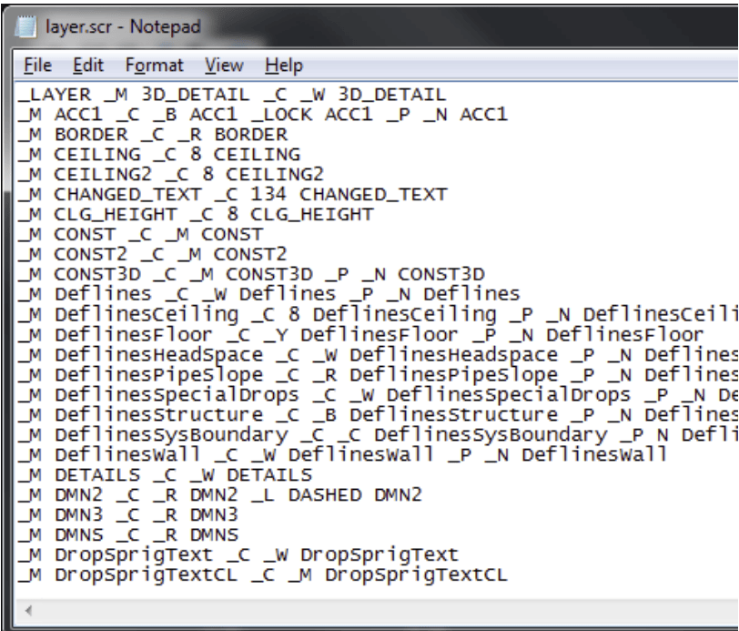
The Layer Script, as mentioned earlier, is a series of commands which are echoed to the command line just as you would type them in, only far faster. Picking HydraTools->Options->Edit HydraCAD Layer Script… will open Notepad with the LAYER.SCR file loaded.
Look at all that gobbledygook! Each phrase is a command, and each blank space is an <Enter>. And that is where things can go wrong. If the wrong letter is used, or an extra blank added, none of the layers may get created, or created using the wrong properties. If you are game, you can try to edit this file but there is a better way.
Automatically Generating the Layer Script
The Layer Script file can be automatically be created from your own template or any drawing you choose. Simply open up the drawing and pick Create Layer Script from this Drawing. The layer script will be auto built using the colors, linetypes, plot or no plot status, line-width and names of new layers that you have created in that template or drawing! That’s it, all done.
What if Something goes Wrong?
We thought of that. Since the Layer Script is so sensitive to changes, we included a command to put it back to the way it was installed, and that is the Restore Original HydraCAD Layers command. You can now try your changes again, with that safety net underneath you.
Q: On the Miscellaneous tab I put the following, thinking I would get twelve 1″ diameter 21’ pieces of pipe…
Quantity: 12 PN: 00004DB110 (the part number for 1″ schedule 40 domestic pipe) Description: 1” diameter Dom Blk Sch 40 Pipe
…Thinking I would get 12-21’ pieces of pipe. However, the processed list only listed 12 FT of 1” pipe. Did I input this wrong or is this a glitch in the program?
A: The units for that item is set to ‘FT’ (for feet) in the Part Number (P/N) table. So, all quantities entered are assumed to be length based. If you need a count of items, then you need to set the units for the parts to ‘EA’ (for each).
Note: If you are pricing material with HydraLIST, the cost is based on the units. With the units set at FT the price is based on a foot of pipe. With the units set at EA, the price is based on the stock length of pipe (21′, 24′, 25′, etc). The default database has both unit length and stock length part numbers created.
Furthermore, if the part number is used as a pipe type option for mains or lines then the units are required to be ‘FT’. Many of our customers carry pipe in 21’ 24’ and 25’ lengths. When the mains and lines are entered, the appropriate pipe type is selected based on the pipe description which includes a stock length. Our default units are setup based on this use.
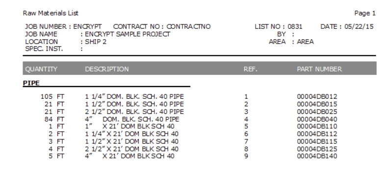
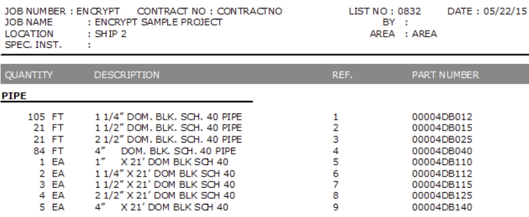
Below is an example where I first listed Schedule 40 Domestic pipe in the traditional Lines and Mains tabs, and also added pipe in Miscellaneous where the units were the default of ‘FT’.
I then changed the units of the parts in my database to EA for the stock lengths of the pipe part numbers and processed the report again: Before:
After:
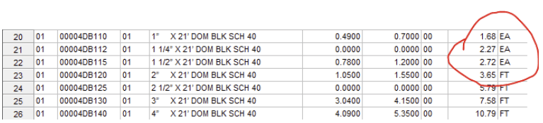
Note that the last five items now report the units of EA as opposed to the default of FT.
How to change the units? Here is how:
1. In HydraLIST, pick the General Data button:
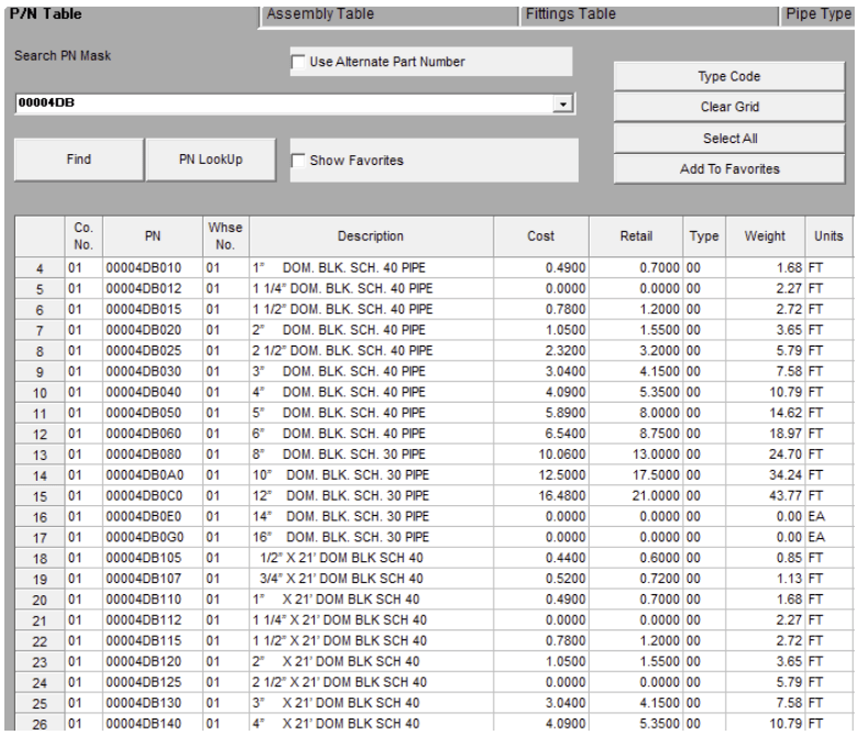
2. Put in the first few characters of the Part Number into the Search PN Mask field and pick Find. This will help you find the exact parts easier. In the example below, I put in 00004DB.
In this view you can see both the per unit length and stock length parts
3. In the Units field, simply double-click on the FT and type in EA. I did that on three diameters of pipe, below:
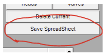
4. Pick the Save SpreadSheet button, then pick the Project Data button and your changes will be saved. Note that this means you will use a different part number for the stock (Miscellaneous) lengths as opposed to the by length pipes (Lines and Mains)
Last year we added a new feature to HydraCAD that allows users to add Fittings, Valves and Backflows to the drawing in order that they may be picked up in AutoCalc and brought over to HydraCALC. The command is Add Calculation Fittings from the Calculation toolbar:
Pick this command. This will display a dialog box explaining the steps needed to add these fittings:
Step 1 is Raise the Drawing to 3D. Pick this button if your drawing is not already in the System Model mode. Then, pick the Add Calculation Fittings command again.
Step 2 will Add or Remove fittings to the pipe you want. Pick this button. You will be asked to select the pipe to add fittings to. In the example below, I am picking the riser pipe.
After selecting the pipe, you will be asked to select the fitting, etc, to add. Note that this is the same dialog box found in the HydraCALC standalone program:
If you want to remove fittings, pick the Clear button and pick OK or select new fittings
Step 3 is used to return the drawing to 2D
Step 4 is an optional step that will scan the drawing an add text alerting you to which fittings have been added, and where. This is not necessary for the proper operation of the program, but is simply there for your own information: