After downloading a file, it is often Blocked. You must right-click on it, pick Properties and then check the Unblock item: But doing a dozen or more files gets old, real fast. I just learned a way to Unblock a batch of files at once. It involves using PowerShell, a Microsoft tool that is a…
If you want to use a new type of hanger, or are a fab shop that gets a job from a contractor that uses a hanger type that you do not have, it is easy to add that new hanger type to your own machine. A hanger is an assembly, and an assembly is just…
Recently our previous blog service (Typepad) ended their business – so, we have a new home. It will take a bit to get images back and displaying properly, but we are working on it! Final pageview count of original Typepad blog: 387,232
Want to keep riser nipples from showing both center and cut length when plotting? Tried to freeze or turn off layers?
AutoCAD has a newish feature that will help you do just this. Its call VP Freeze for Viewport Freeze.
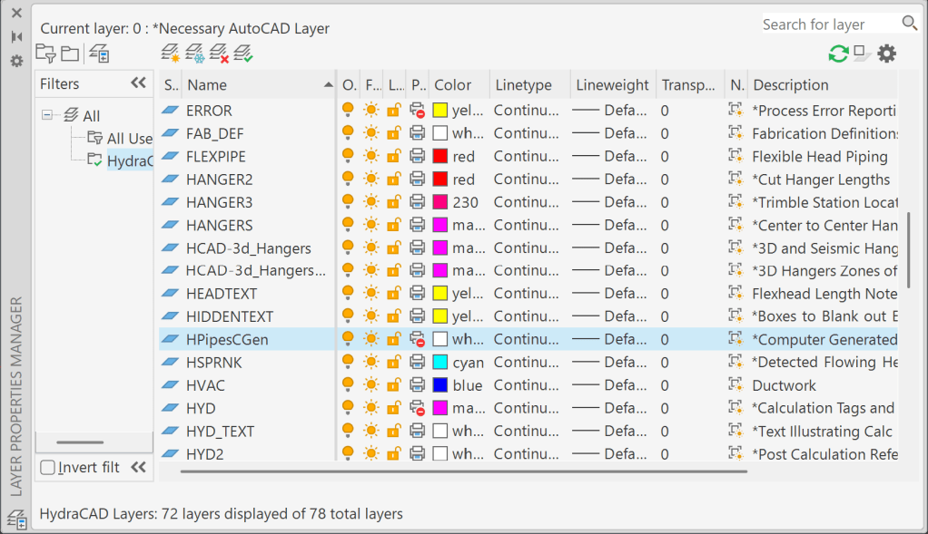
Open the Layer palette. Find the HPipesCGen layer. Click the Square Sun icon in the New VP Freeze column. This will freeze this layer in viewports!
This modification has been added to HydraCAD V56.04 and V55.05. A change made to HydraCAD templates and layer script so that the HPipesCGen layer is set to default this way.
Many of us use Copy and Paste in AutoCAD. Often when using Paste, we try to eyeball and line up the block we are pasting, or use OSNAPS.
But there are better ways!
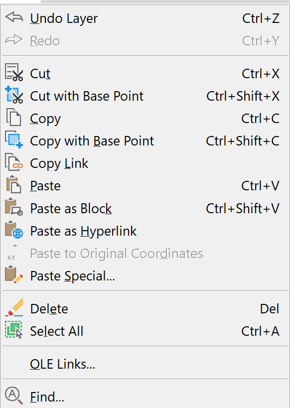
The Edit drop down menu in AutoCAD has more than one command to copy and paste:
Cut is cut
-but-
Copy is copy without a specific base point. This makes it hard to align and place properly
Copy with Base Point allows you to select a base point, making it easy to line up the block between sheets or other objects
Paste asks for a placement point, you have to eyeball it or make sure you used Copy with Base Point so you can line up properly
Paste as Block brings in all that was Cut or Copied as a single entity
Paste to Original Coordinates is handy, as it does not require that you specify a base point. Say you need to copy the plan view of a stairway detail from one drawing to another, and naturally, you want to keep the valve and piping arrangement in the same relative position on each drawing. This is where Paste to Original Coordinates comes in handy
Note: You can also use the Copy with Base Point command from the same drop down. Select a common reference point, like the corner of the stairway. Then use the Paste command and you will see that your cross-hairs reflect that point.
Some customers need to produce a modified Raw Materials List to send to their accounting department so the items can get inventoried and/or billed. Here is how you do that:
*Note: These steps are outlined in the HydraLIST manual in the How Do I? section*
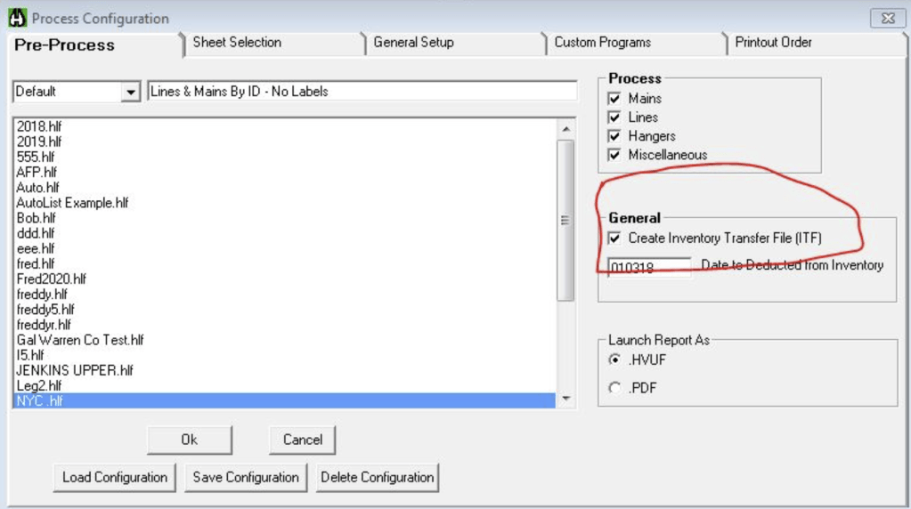
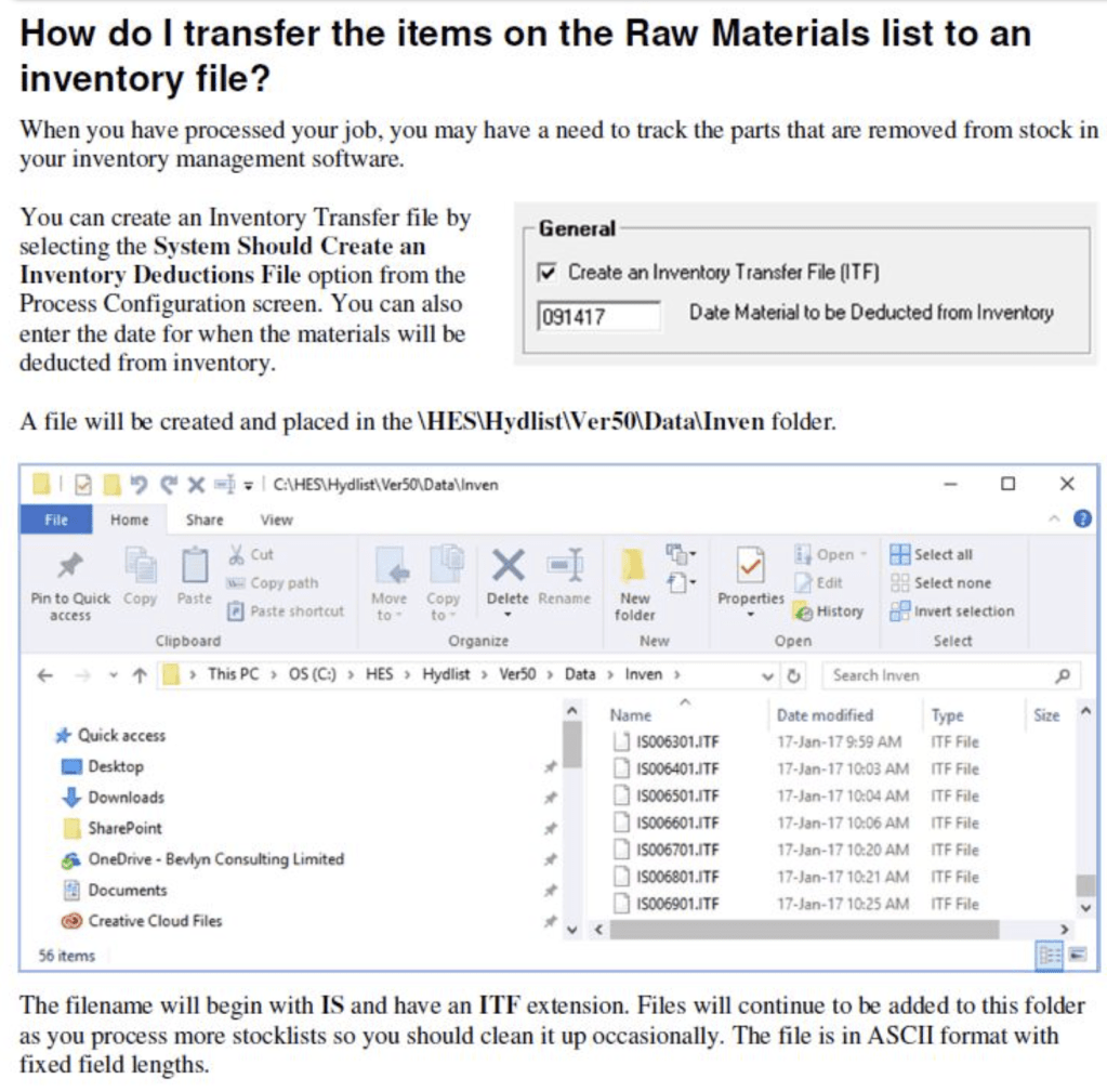
When the user processes a job, they need to check the Create Inventory Transfer File (ITF) option
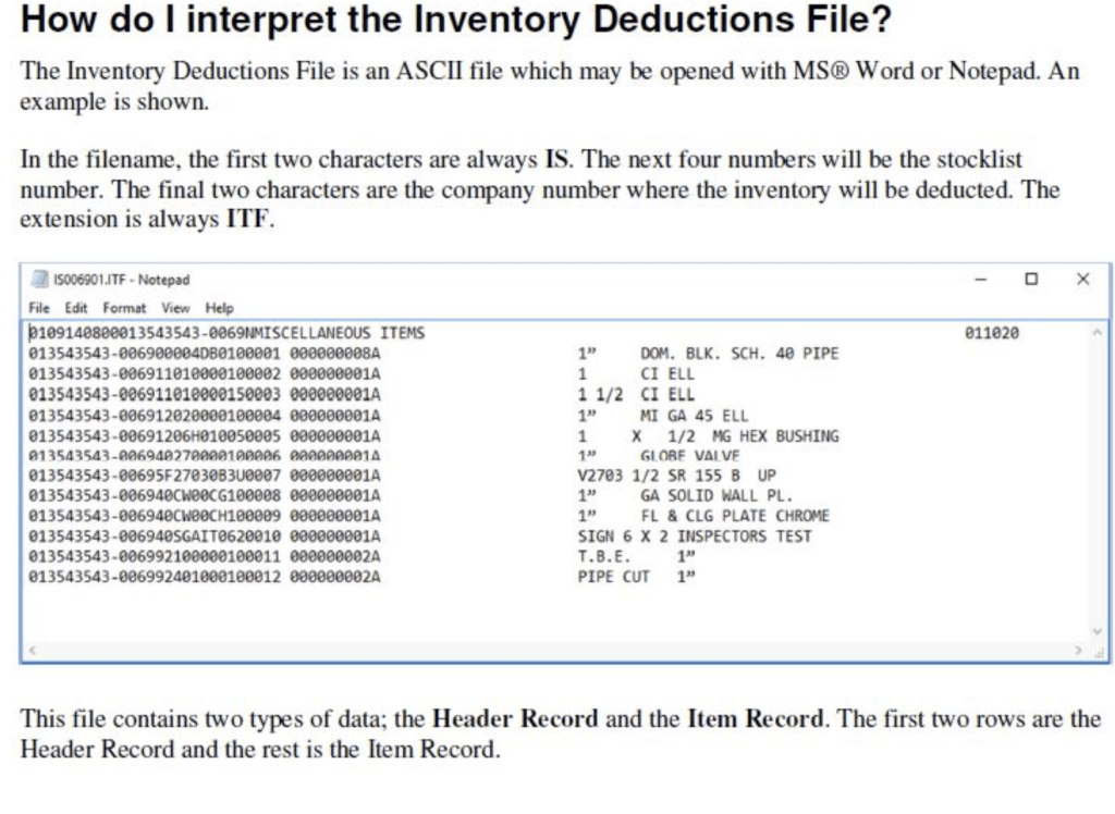
This will create a small file in their \HES\Hydlist\Ver50\Data\Inven folder, that matches the Job Name and has an extension of ITF. This is an ASCII text file and can be opened in whatever you like.
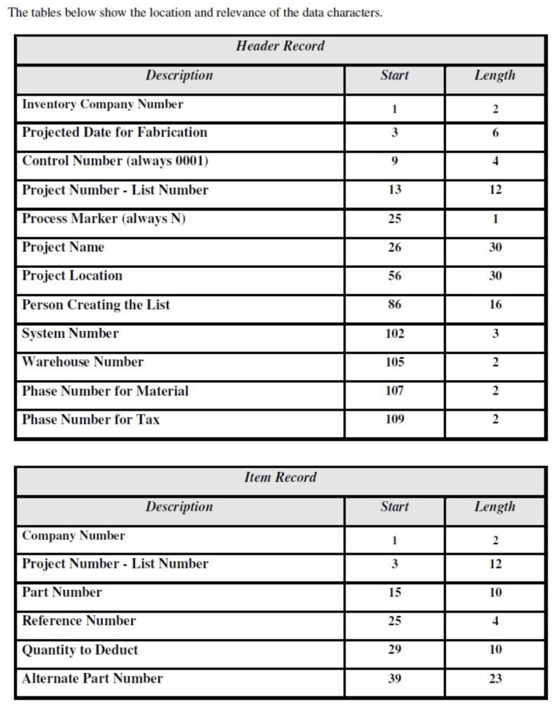
Here is how you read that file
From the HydraLIST Manual, pages 8-283 through 8-285
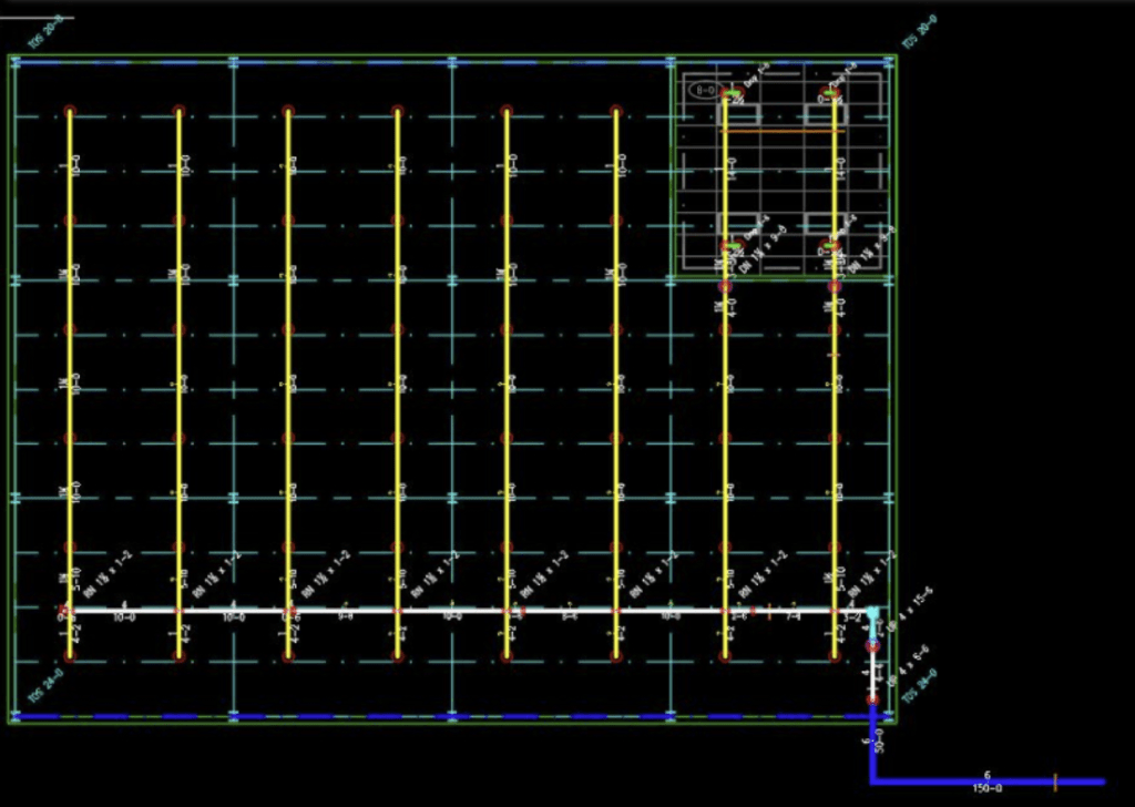
In even a regular-sized drawing it can be hard to determine what is a main, what is a wall, what is a partition, etc. Some people use the Pretty Pipes command to help with this, but that has a few drawbacks, especially when it makes it hard to select objects.
Lineweights can make that easier, it updates automatically as new piping is drawn and it does not add any drawing elements, making selection easier.
In this small drawing, note the unremarkable look of the Lines and Mains at left:
With Lineweights turned on, it looks like this:
The lines and mains pop out and are easy to recognize. Underground and Armovers also stand out, if present.
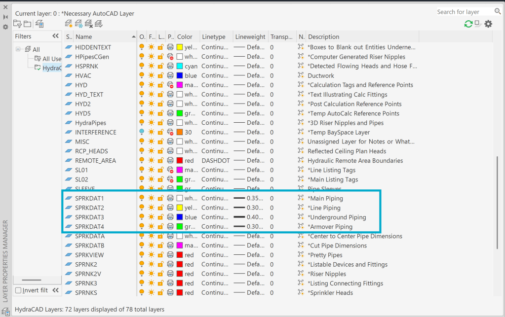
Lineweights are defined by layer. Opening up the Layer palette, note the Lineweight column.
These are the default HydraCAD layers, as defined in our templates and layer scripts. If you do not see the Lineweights defined, you may be using an old template.
The LWDISPLAY command applies these Lineweights to the drawing elements.
Type it in, and answer ON to see the lineweights, or select the Show / Hide Lineweight button on the bottom of the AutoCAD screen.
If you do not see this option, select the Customization button at far right and select LineWeight to turn it on
HydraCAD and AutoCAD both have methods of creating typing shortcuts/aliases to commands. HydraCAD does not deliberately use the same key sequences as AutoCAD. I say usually, because sometimes AutoCAD adds new shortcuts which share our Aliases. We don’t change ours to stay out of their way. HydraCAD aliases take precedence because of the way each program is loaded.
The AutoCAD aliases can be easily changed. Many people (including myself) change ‘C‘ to be COPY instead of the default CIRCLE, for example.
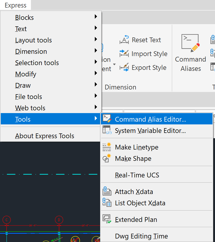
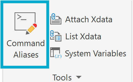
The AutoCAD aliases are stored in the ACAD.PGP file in the \Program Files\Autodesk\AutoCAD 20##\UserDataCache\en-us\Support folder, where ## is the last two digits of the version of AutoCAD you are using. You can best edit this file by using the AutoCAD Express tool Command Alias Editor from the Ribbon or dropdown menu, or by typing in ALIASEDIT.
HydraCAD aliases are in a different file, named HC_ALOAD.LSP, located in the \HES\HydraCAD\Ver50\Programs\Version## folder, where ## is the version of HydraCAD you are using. It can also be customized by using a text editor (like NOTEPAD), but you must be more careful when editing this file than with the ACAD.PGP, as ours uses actual programming language.
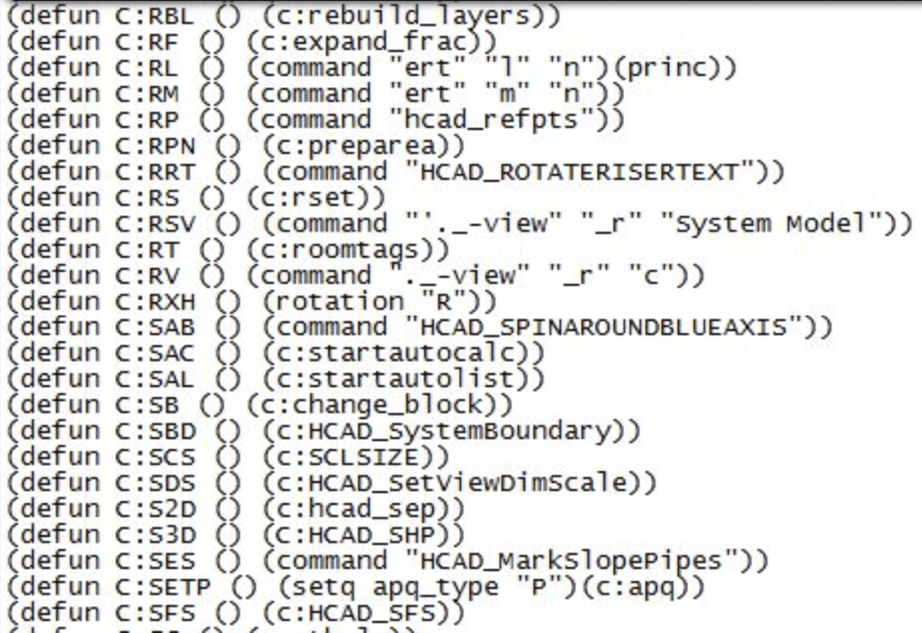
Opening HC_ALOAD.LSP, you will see we use LISP functions to create them.
Example:
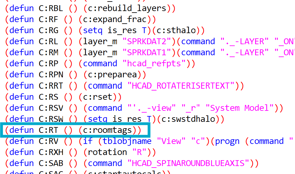
You want to use the key sequence RT as an alias of ROTATE. RT already used by HydraCAD for Roomtags, so you will have to Add RT to the AutoCAD alias list (ACAD.PGP) and either remove it from the HydraCAD list or rename the existing HydraCAD sequence to something else.
Before you open the HC_ALOAD.LSP file, save a backup copy of it, in case something goes wrong.
Locate the RT alias in the HydraCAD list. Now, change RT to be RMT. Save the file. Next time you open AutoCAD, RMT will start the Roomtags command.
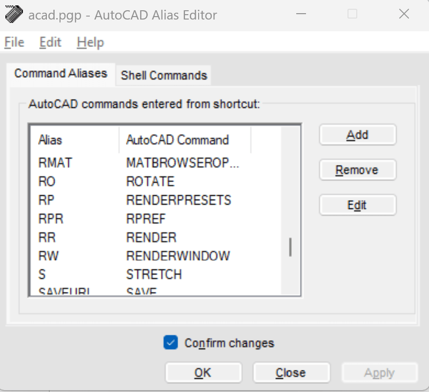
Open the ACAD.PGP file using the express tool mentioned above.
Scroll down to the Rs. Notice that RT is not being used for any other AutoCAD command.
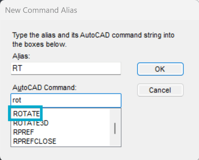
Pick the Add button. Type in RT in the Alias field and begin to type ROTATE or scroll through the list of commands available in the AutoCAD Command: field.
Pick OK. Pick OK again. Close AutoCAD/HydraCAD and reopen. Your alias should work now.
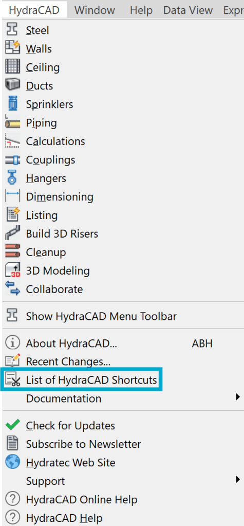
PS – A complete list of HydraCAD aliases can be found by picking the List of HydraCAD Shortcuts command from the HydraCAD pulldown menu. You can edit this file to update this list to reflect your changes. Future updates will probably replace this file and the HC_ALOAD.LSP file, so make sure you have copies of your work to bring back if necessary.
A Customer asked me the following question (paraphrased):
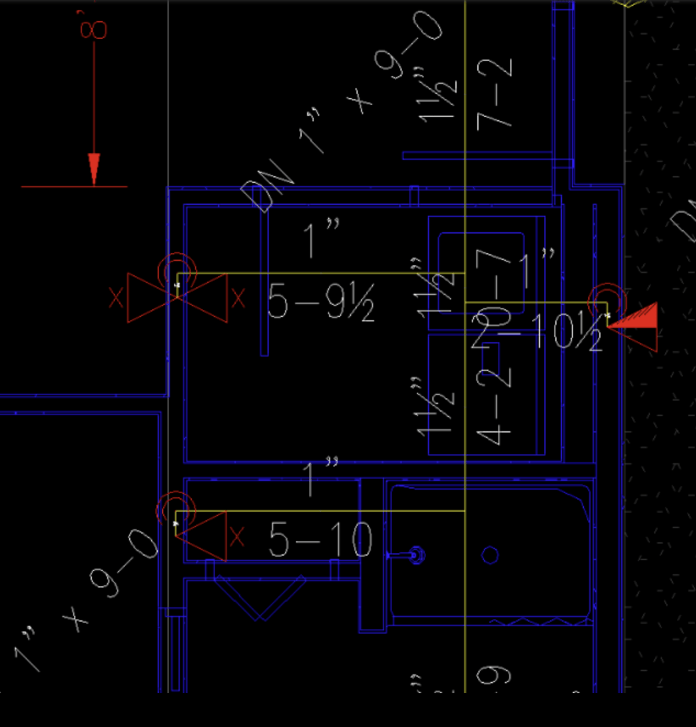
Q: I am currently designing an apartment bldg using sidewall sprinklers for the top level. And this is also a BIM project so our piping is imported into Navis Works. If you look at the attached sidewall 2D photo. You will see that I have the sidewall attached to piping inside of the wall. (this is so HydraLIST will list the fitting as a 1 x ½ CPVC sprinkler elbow). However in my model the piping and sprinkler are hidden inside of the wall. … (I would like to) make the sidewall sprinkler protrude from the wall so it is visible in the Navis Model.
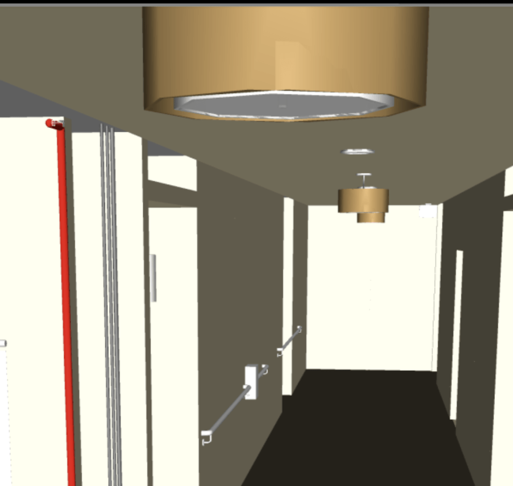
I removed a wall panel in Navis so you can see the pipe and sprinkler in the attached sidewall model photo:
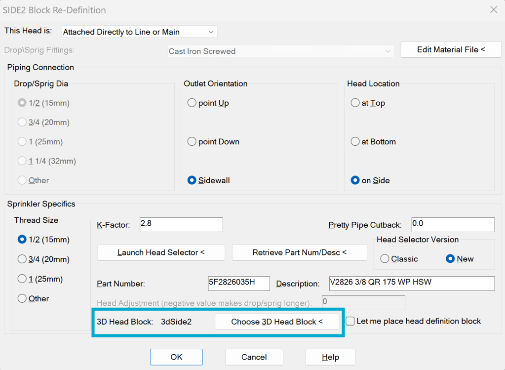
A: The solution here is not to modify the piping arrangement in 2D so that the 3D model looks the ‘right’ way. The key is to instead modify the 3D Sprinkler Head Block. When you define a sprinkler head, one is already chosen for you as a default. You have the option to specify which 3D head will be used:
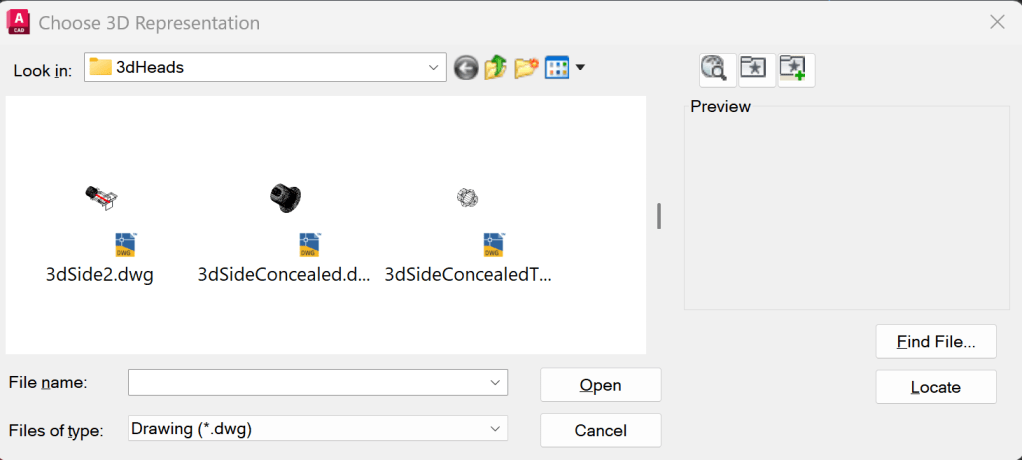
If you pick ‘Choose 3D Head Block <‘, you will be directed to the \HES\HydraCAD\Ver50\Programs\HEADS\3dHeads folder. There, you will find two or three dozen 3D heard representations. These are assigned to each defined sprinkler head type when created. They show in the 3D model generated when you raise the building up.
Find the representation closest to the head style you want and then open that drawing directly in HydraCAD. Modify it as you see fit and do a SaveAs to give it a new name (so you don’t replace any of our default values).
There are two overhauled commands in AutoCAD 2020 that are used pretty often. One of the is the PURGE command. The other is INSERT, which I will mention in a future post.
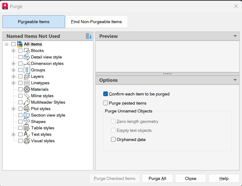
A customer had trouble getting the rings and other elements of hangers to show up properly when they ran 3D Hangers. I am still not sure how the problem occurred, but the gist is the hanger rings were somehow defined as other objects. My co-worker, Bill McKenna, suggested that might be the problem, so I used the new Purge command to track them down. Here is how I figured out which blocks were mis-defined and fixed them.
In the drawing, I typed in PURGE. It takes a little while to load up, because it does a great deal of drawing scanning
Note the selection tree that shows up. Kind of cool.
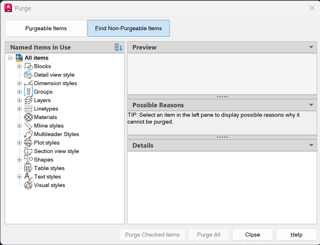
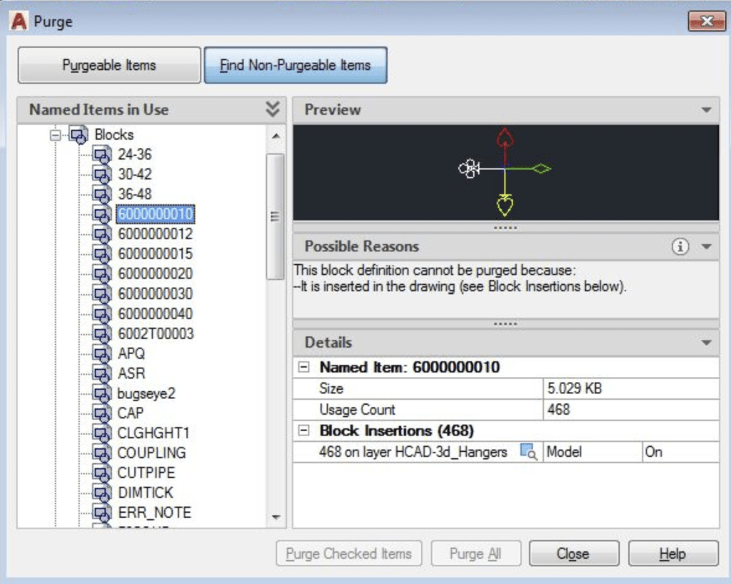
I picked Find Non-Purgeable Items to see what Blocks might be candidates
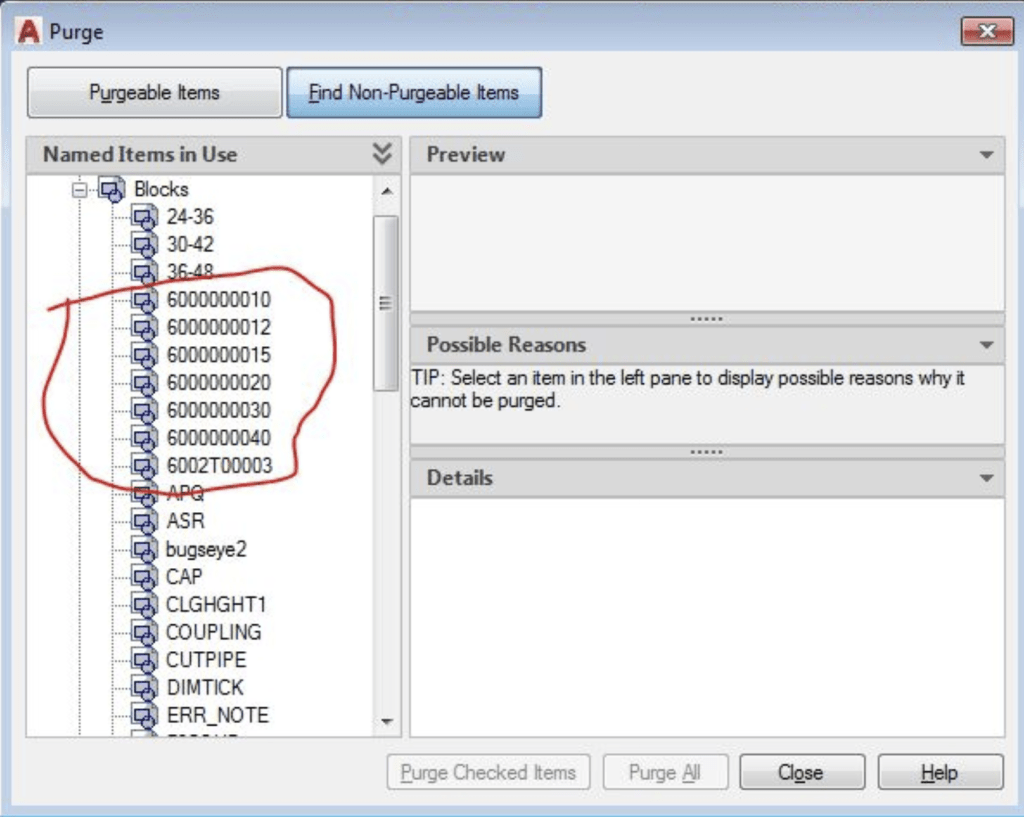
I then picked the + next to Blocks.
Many of the first few defined blocks really stand out; 60 is the part number category for Hangers, making these likely candidates.
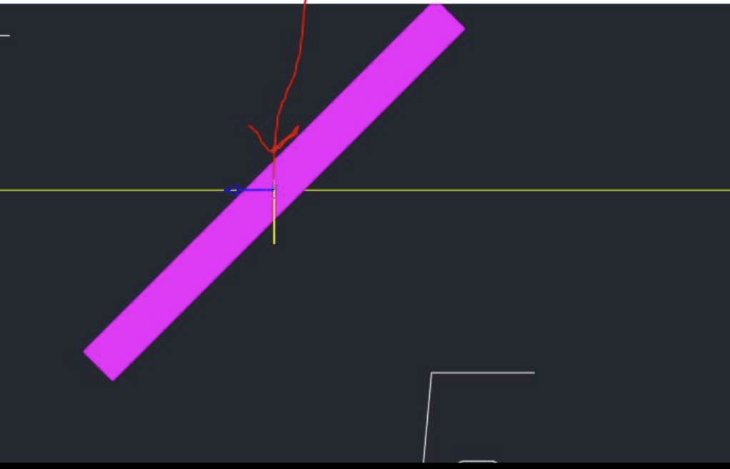
Picking the first one shows what is wrong right away. The hanger ring (10 being 1 inch) is somehow defined as a ski-pole. The solution is to erase all seven ’60’ blocks (one for each size) and purge them out. Except, they cannot be purged because they are inserted in the drawing.
So, I turned all the layers on using the AO (all on) command. I then type in DL for Delete Layer and selected one of the ski-poles inserted where the 3D hanger ring should be. This deleted over 4000 items from the HCAD-3d_Hangers layer.
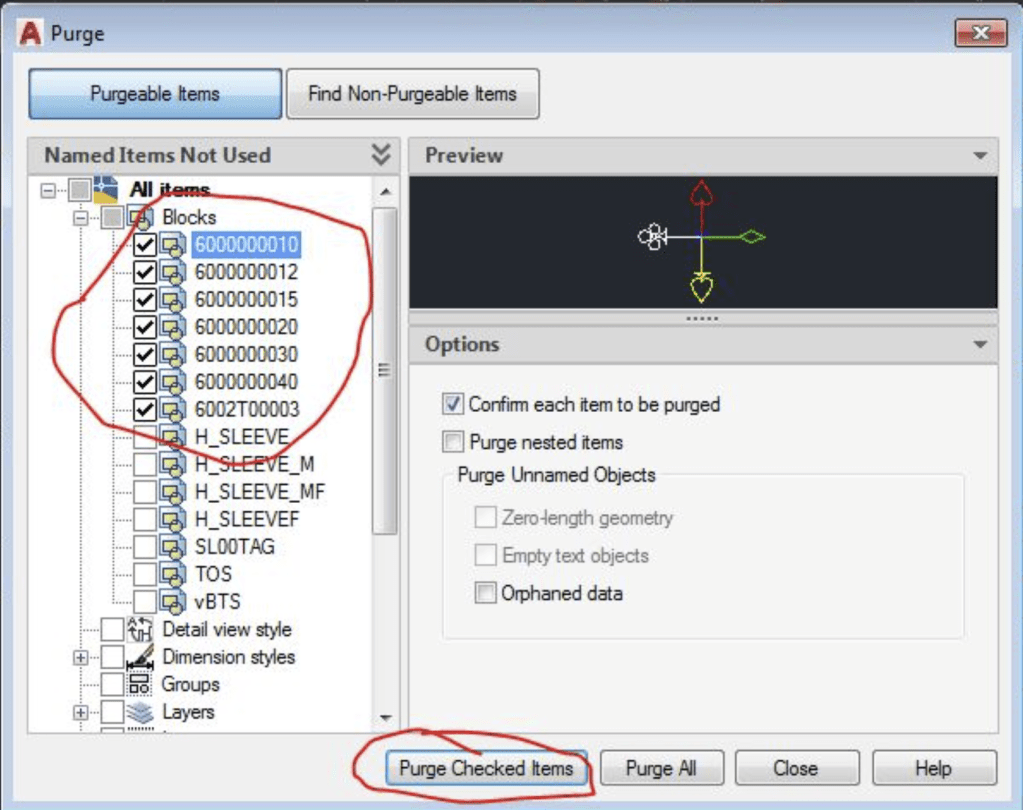
Now I could to a PURGE again and be able to select the mis-defined blocks and purge them.
i checked each of the seven ‘bad’ blocks and picked Purge Checked Items. I was now able to create the 3D Hangers properly.
Many IT professionals like to ‘push‘ installs onto user machines, as they don’t want to sit on each user’s machine and click the Next and OK buttons repeatedly.
There is a way to record the steps used to install our software, and replay those steps on each user’s station.
The Silent Install options for InstallShield installer
Switch
Notes
/s
Silent mode. For an InstallScript project, the command Setup.exe /s runs the installation in silent mode, by default based on the responses contained in a response file called Setup.iss in the same directory
/r
Record mode. In order to run an InstallScript project installation program in silent mode, you must first run Setup.exe with the /r option to generate a response file, which stores information about the data entered and options selected by the user at run time. Running an InstallScript installation program with the command Setup.exe /r displays all the run-time dialogs, and stores the data in a file called Setup.iss, created inside the system’s Windows folder. response file name and location, use the /f1 option, described below.
/f1
Specify alternative response file name and path Using the /f1 option enables you to specify where the response file is (or where it should be created) and what its name is, as in Setup.exe /s /f1″C:\Temp\Setup.iss”. Specify an absolute path; using a relative path gives unpredictable results. The /f1 option is available both when creating a response file (with the /r option) and when using a response file (with the /s option)
/f2
Specify alternative log file name and path When running an InstallScript installation in silent mode (using the /s option), the log file Setup.log is by default created in the same directory and with the same name (except for the extension) as the response file. The /f2 option enables you to specify an alternative log file location and file name, as in Setup.exe /s /f2″C:\Setup.log”. Specify an absolute path; using a relative path gives unpredictable results.
Example: Start the installer silently
Setup.exe /s
*Note*– The HydraCAD for AutoCAD and Hydratec for Revit installations actually install three major products. The HydraCALC program is found in a folder in the packet of install files, as the HydraLIST is also found in its own folder. For now, three scripts will need to be recorded and run, one for each. These steps will outline the process:
As always, extract the contents of the installation package (.ZIP) to a folder on your hard drive
Move the HydraCALC folder out of that folder into another folder
Move the HydraLIST folder out of that folder into another folder
Run each of the three SETUP.EXE programs (inc. HydraCAD in the original folder) with the proper command line switches and record each one individually
Run each of the three SETUP.EXE programs independently with the proper command line switches to install per the recorded file
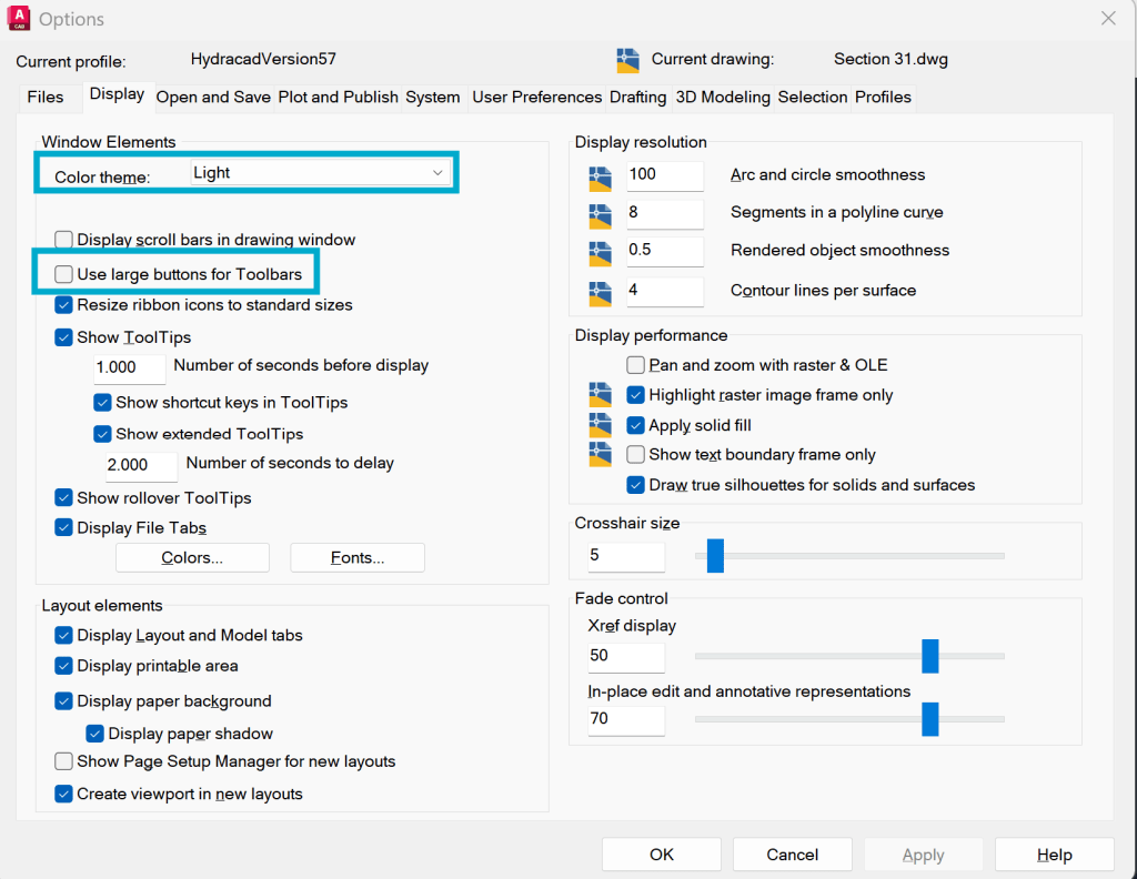
AutoCAD has a Dark Color theme and a Light theme. In all, there are four basic configurations. Dark and Light, regular and large buttons. These are accessed via the OPTIONS command (type in or right-click on the Command: line). They are found on the Display tab.
The default is the dark theme with regular-sized buttons, which some find hard to read, so they choose the large buttons. Or they choose Light with either large buttons or not. These four look like:
Light Theme / Large Buttons
Light Theme / Regular Buttons
Dark Theme / Large Buttons
Dark Theme / Regular Buttons
For a large monitor, the large buttons work best. For a laptop, I’ve found the regular size to be best, as the large are too large to all fit. Personally, I recommend large dark over regular dark, as I find the regular dark to be almost unreadable. If you are going to go ‘regular’, I recommend the Light theme.
Also notice the Ribbon buttons do not get larger by selecting Large.
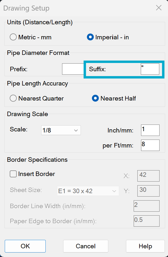
From a Customer: “Where is the setting to get the inch prefix when I am using the change pipe diameters? Every time I have used this command with 2019 it takes away the inch suffix when I select a pipe size to change.”
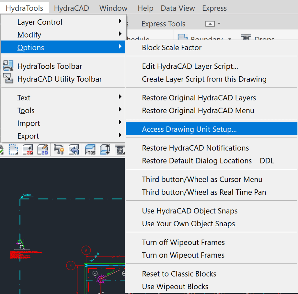
Answer: The place to set it is there when you start a new drawing. You can also access it by picking HydraTools->Options->Access Drawing Unit Setup:
Note: This does not have anything to do specifically with 2019, but it can be easily changed, more or less permanently.
Put a “ in the Suffix field
The next time you go up to 3D and back to 2D, the suffixes will be updated to reflect your choice.
Note: The Prefix option is more or less only used by our Metric friends in Europe. They sometimes use it to put a nominal diameter symbol in front of the pipe diameter, i.e. ø25
Also: This command can also be used to change the drawing scale if you set it up wrong