If you want to use a new type of hanger, or are a fab shop that gets a job from a contractor that uses a hanger type that you do not have, it is easy to add that new hanger type to your own machine. A hanger is an assembly, and an assembly is just…
Recently our previous blog service (Typepad) ended their business – so, we have a new home. It will take a bit to get images back and displaying properly, but we are working on it! Final pageview count of original Typepad blog: 387,232
A customer called today asking how to enter a 1″ black plastic underground pipe for the calc. This particular situation sounded unique enough that I did not tell him to add that pipe type to our database, as I would have if he expected to see this pipe type used repeatedly. I told him to…
Today’s customer question: “How do you draw an Up/Down sprinkler (Upright on a Tee, with a Pendent Drop) in HydraCAD?”
This is actually easier than it seems. You just have to define the two heads, as usual, and insert them at the same X,Y location (i.e. on top of each other).
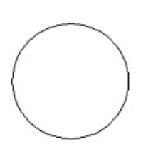
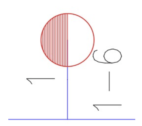
Back in the ‘old days’, designers would draw such a combination using this symbol:
In this example, we will create the same symbol as far as looks are concerned
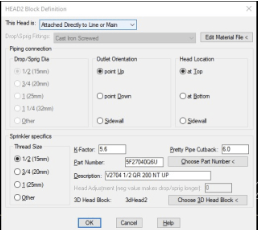
1. Define the Upright head like usual. We suggest using HEAD2 if you haven’t already. That is the symbol that looks like this:
This head should be defined as Attached Directly to a Line or Main
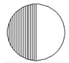
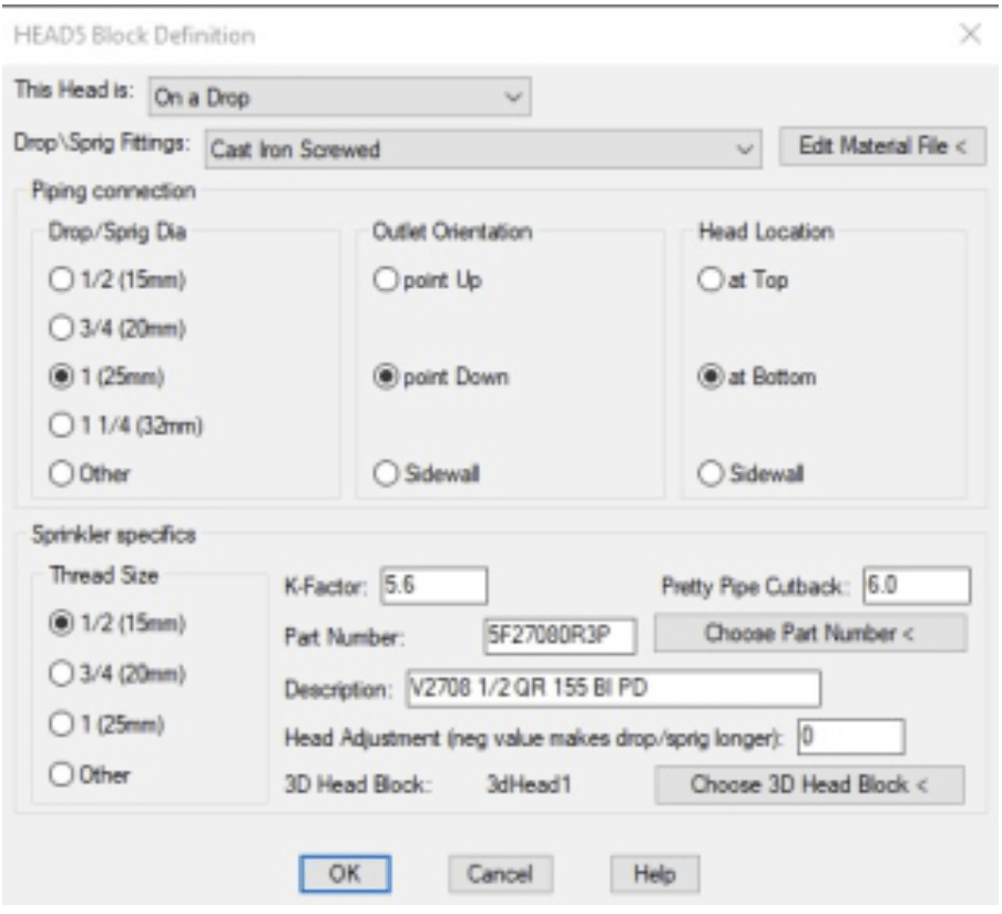
2. Define the Pendent head like usual. We suggest using HEAD5 if you haven’t already. That is the symbol that looks like this:
This head should be defined as On a Drop
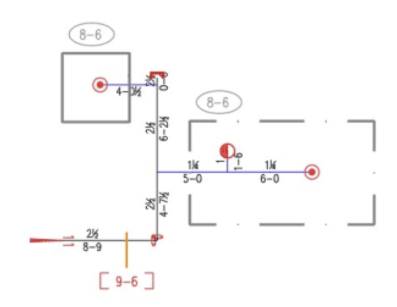
3. Insert one of each of them at the location of the bullhead tee. Notice this looks exactly like the old-school head at top
4. Insert a Drop Window around the pendent head(s). Remember that a drop window will only affect heads on a drop, so it is ignored in the case up upright heads
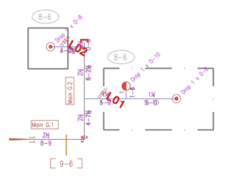
5. Tag it for listing and run it through!
Notice the Drop was tagged with its info
In HydraLIST, this is what got picked up:
Note 1: If you need an upright on a sprig at the same X,Y location as the pendent, then you would defined HEAD2 as being On a Sprig. You would also place a spring window (using the Drop Window command)
Note 2: If you already used HEAD2 or HEAD5 for some other head definition, you can make create other heads that look the same. Find that info here: Creating Sprinkler Heads
“I am trying to create a Trimble point layout for my beam clamps only. Is there anyway to isolate the #01 Hangers from the #05 Hangers?”
While there isn’t a direct way, there is an indirect one. There is a way to grab a selection set based on an attribute value. This involves one of my favorite commands: FIND
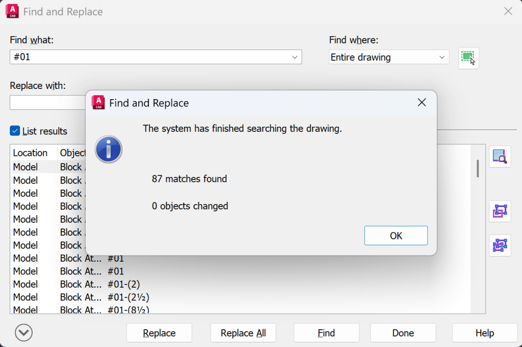
Type in FIND. Press Enter
Check the List results check box. This opens up the bottom half of the above dialog
Type #01 in the Find what: edit field. Hangers are easy because of the formatting of the text, there isn’t any other text that looks like #01
Pick the Find button. This gives you a count of the values that match your search string
Pick OK
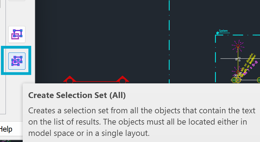
Pick the Create Selection Set (All) button at right. You can also select individual items from the list and pick the Create Selection Set (Highlighted) if you need to fine-tune which blocks get selected
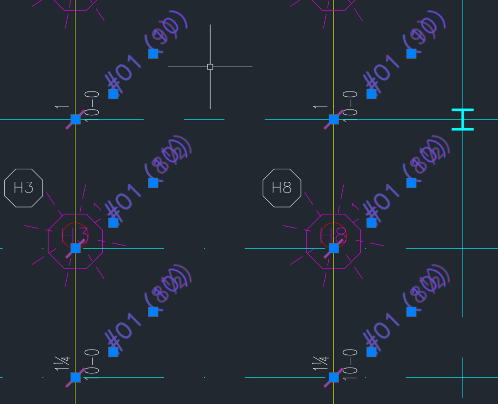
This gives you a selection set of all the items that have the string #01 in them, zoomed in
You could then move these objects outside the boundary, by a specified amount and moving them back again when you need to
Please also see this post on how to change Hanger numbers for already inserted hangers: Changing Hanger Numbers
“I’m having issues with HydraLIST keeping my rod cut lengths to the ½” length I assign it even with noting it as “CL”. It wants to always round up to nearest inch. This is primarily the 06 hanger I’m using. Is there a setting that forces this rounding?”
The answer is yes, there probably is. It may be a default setting in the data we ship, or it may be a company setting your organization created.
To the point, some companies use studs instead of cut rod for inch or two-inch length up to a certain value, like 6″ or 12″.
The documentation that covers this is in the HydraLIST manual which can be accessed by picking the Help pulldown in HydraLIST. This topic can be found on page 7-223. In it we look at a Type 01 hanger, but the rules apply to the other hangers as well. Viewing or changing all setup rules in HydraLIST is done by accessing the General Data by using the button shown below:
This is what it tells us:
The Makeup of a Type 01 Hanger
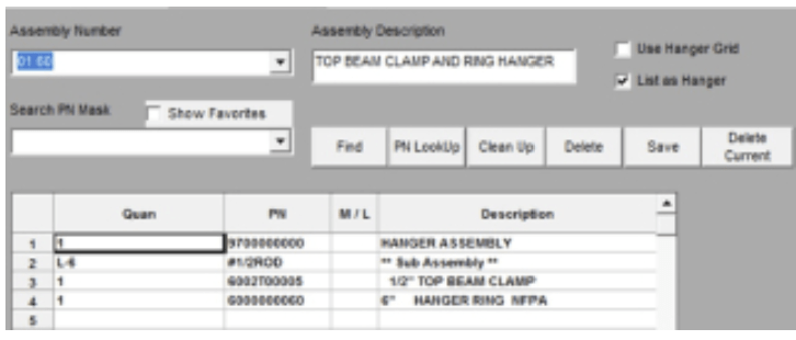
In HydraLIST, pick the General Data button. Select the Assembly Table tab with Use Hanger Gridnot checked. Pull down the Assembly Number list and select the 01 60 hanger. This is a top beam clamp hanger which is a type 01 hanger. The 60 in the assembly number indicates that it is a hanger for 6-inch pipe.
The list of parts for this hanger appear in the lower section of the screen. There are part numbers for a rod, a 1/2″ beam clamp, a 6″ hanger ring, and a part number for the labor required to build the assembly.
If center-to-center distances are selected in the Hanger Project screen, the rod cut length must be calculated. For this reason, this item must be entered in a special way. Under the Quantity column is the formula L-6. When the hanger list is processed, the computer looks up the center-to-center distance from the Hanger Project screen, and subtracts 6 inches from it for the pipe ring takeout. The length remaining is the cut length of the hanger rod.
If cut length entries are entered in the Hanger Project screen, then L is taken as the length of the hanger rod and no takeout calculation is performed.
Hanger Sub-Assemblies
Note the part number for the threaded rod entry. It is #1/2ROD. This is a sub-assembly which is used so that the correct rod part number may be pulled from stock based on a range of sizes. Any assembly which begins with a # is a sub-assembly.
View the #1/2ROD assembly by finding it in the Assembly Number pull down list.
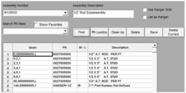
This is the #1/2ROD sub-assembly which ships with HydraLIST. The Quantity field specifies the range of lengths that are valid for the job entry. If the entry falls within the criteria, then the third character is executed. For example, on the first line the Quantity characters are 0,99999999,L. This is interpreted as any rod from 0 inches to 99999999 inches (a very long length!) is to be processed and printed as the length (L) entered in the Project screen. Note, the criteria in this column must be separated by commas. If you wish to have your hanger rods listed to have lengths as entered in the Project data screen, then use this option.
With the first line present, none of the other lines are executed since the first line will satisfy any rod requirement.
If your shop prefers to use studs which are pre-cut to length, then delete the first line so that the subsequent lines may be used by the process program.
The next line, Line 2, has an entry of 0,2,1. This is interpreted as any rod from 0 inches to 2 inches long will require 1 of part number 6027005020 to be removed from stock for the job. This part number relates to a 1/2″ X 2″ All Threaded Stud.
Line 3, has an entry of 2,3,1. This is interpreted as any rod from 2 inches to 3 inches long will require 1 of part number 6027005030 to be removed from stock for the job. This part number relates to a 1/2″ X 3″ All Threaded Stud.
This selection of threaded studs continues until 6″ is reached. At this point, line 7 is executed. Line 7 has an entry of 06,99999999,L. This is interpreted as any rod from 6 inches to 999999999 inches (also a very long length) is to be processed and printed as the length (L) entered in the Project screen with the part number 6027005000 which relates to 1/2″ All Threaded Rod.
Notice that all of these rules effectively round the rod length up to the nearest inch (for this assembly). Others may go every two inches, for example.
Please refer to Chapter 7 of the HydraLIST manual for more details about this subject.
Our live HydraCARDs Knowledge Base contains a database that is updated automatically as soon as we update or create them!
Accessing
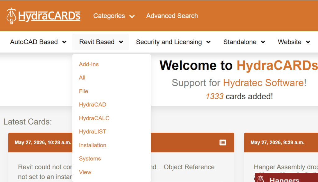
Most of our update and installs now include a shortcut to the web address for HydraCARDs. Further, HydraCAD, HydraCALC and Hydratec for Revit all link to this new database. However, no actual software is required to access the new HydraCARDs. All you need to do is to point your browser at https://hydracards.hydracad.com/
Once there, you will see an easy to read and use the Knowledge Base. The most current cards will be featured right up top.
Browsing by Program
Picking the Categories drop down menu will let you see all the cards pertaining to that program
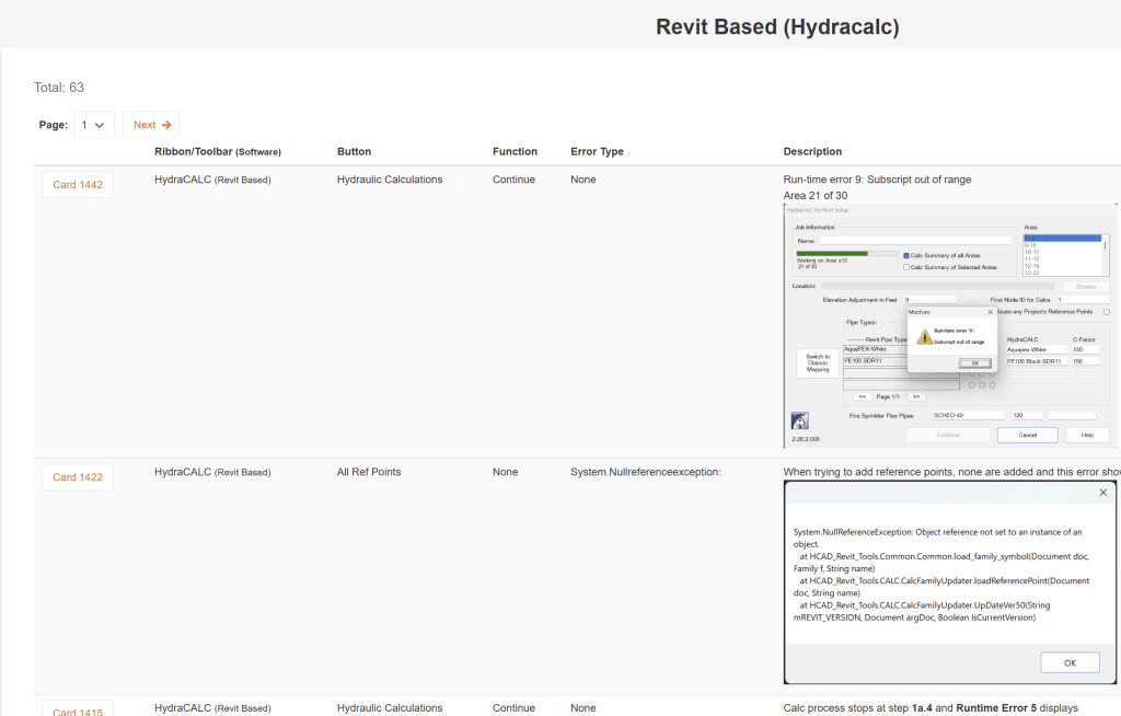
This will display a page that shows all the cards for that program. The total number of cards is at the upper left. The Page drop down will let you skip ahead. The Next button will go to the next group of cards.
The View button at right will open the error card for that one. Notice that cards may include graphics and hyperlinks, making them easy to use.
Saving Your Favorites
If you find a card that helps you, it is really easy to save it so you can find it again. How?
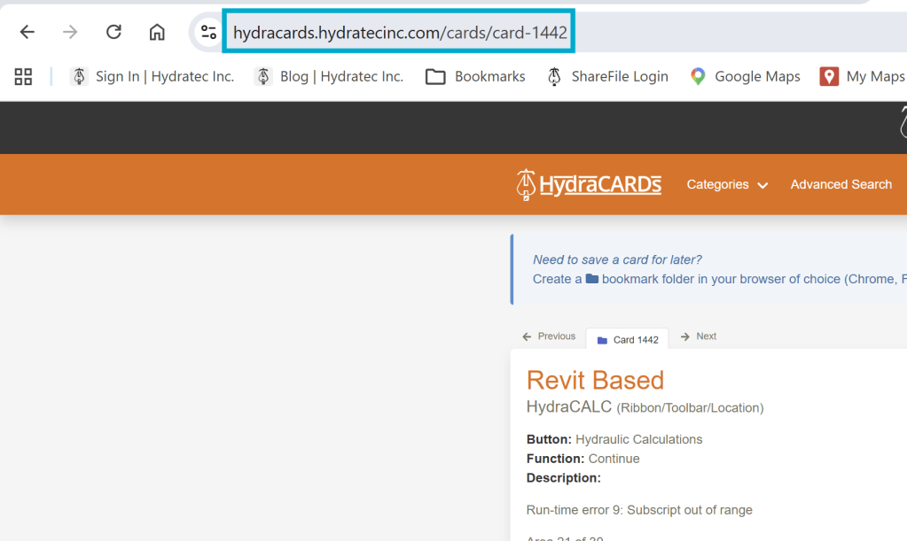
Notice that each card has it’s own URL:
You can save this URL to your Bookmark collections in your Browser.
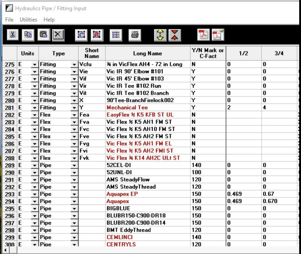
Most users do not realize that HydraCALC has long had the ability for users to look at the tech data sheets for pipe, fittings and curves. These are accessed through the Alter Pipe and Fittings command in the Utilities drop down menu.
To view the tech data sheets:
Pick the Utilities drop down menu
Pick Alter Pipe and Fittings
You will see some items in black and some in red. the black ones have PDF tech data sheets assigned to them, the red do not (yet).
To view the tech sheet
3. Select the item you want to view the sheet for (I usually select the number at the far left, to avoid making data changes.
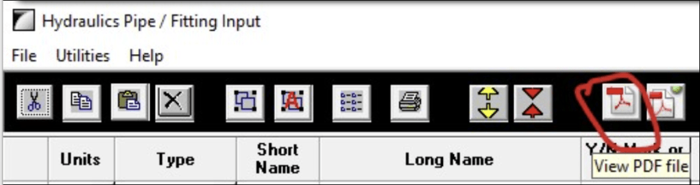
4. Pick the View PDF button (second from right)
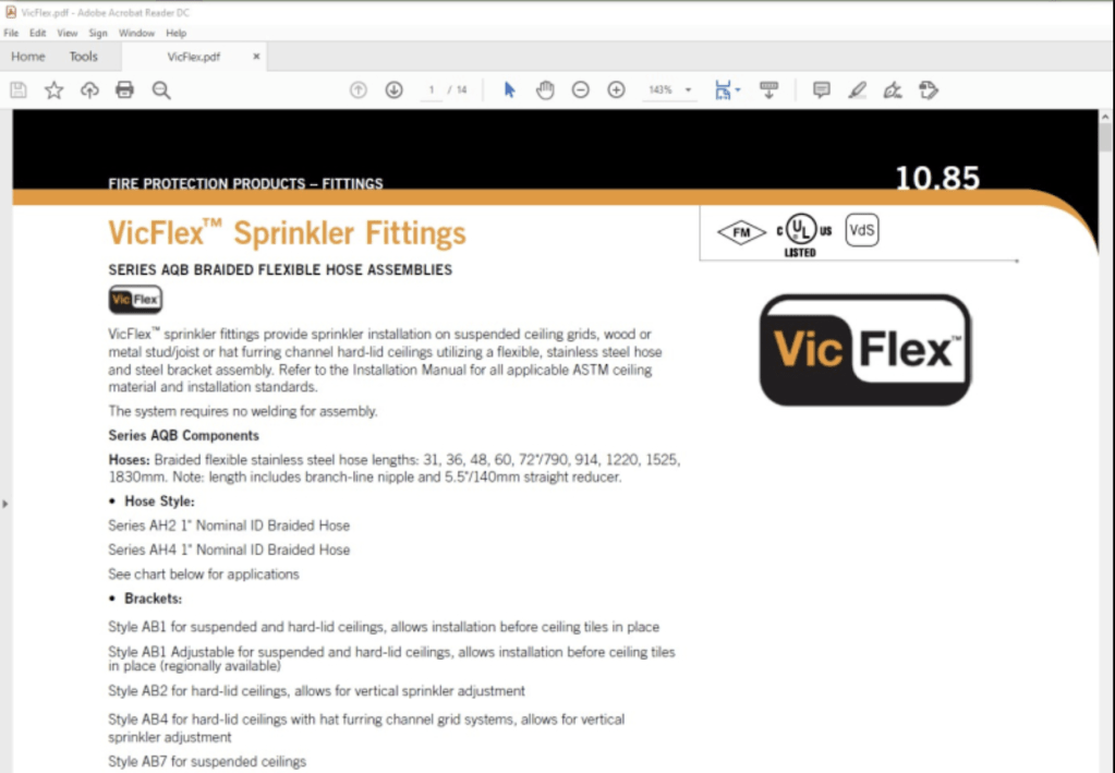
This brings up the tech data sheet!
Notes
Note 1: If you do not see fittings that appear here, or are looking for updated or new ones, you can download the latest from our Support Site or run the latest HydraCALC Update. You will be given an option to update your system with the latest data
Note 2: Users have the ability to reference their own data sheets and add ones as well. However, the tool we include for this can be complex and hard to work with. So, please feel free to ask us to update or add tech data sheets for any items you use or find incorrect. Thanks!
More info:
To see how to reference fittings, here is a blog post showing an example. Again, feel free to ask us to add the fittings for you: How to Add Fittings in HydraCALC
If you are not happy with the colors or line-types of the existing steel, walls, ceilings, structures, etc – then feel free to change them. But, this does not need to be done to use HydraCAD effectively
If the background drawing has existing piping, you may be able to use that piping for HydraCAD.
The ‘may’ all hinges on how the original author drew the piping. Is it from center of head to center of head (or fitting)? Is it from edge of head to edge or head (or fitting). Is it simply drawn through all heads and couplings on a line or main, without stopping at each head? Are they really polylines?
If they are polylines, Explode them first. This will break them into segments.
If they drew the other ways, you can convert them like this:
Step 1: Isolate the layer of the piping by typing PC to pick the current layer, and pick one of the pipes. You can also use AutoCAD’s Layer Isolate tool.
Step 2: Type in AF to turn all the layers off except for that current layer.
Step 3a: Select all of the pipe you want in the Main layer and pick SPRKDAT1 from the layer drop-down list Step 3b: Select all of the pipe you want in the Line layer and pick SPRKDAT2 from the layer drop-down list Step 3a: Select all of the pipe you want in the Underground layer and pick SPRKDAT3 from the layer drop-down list Step 3a: Select all of the pipe you want in the Armover layer and pick SPRKDAT4 from the layer drop-down list
If they are only drawn edge to edge, you will have to turn on all the layer and use Grips or Extend to make the pipes reach the center / insert point of our heads and couplings.
If they are drawn through all the entities, you will have to break them up into segments. You can use AutoLine and AutoMain to do this relatively painlessly.
Say you have a background drawing that has sprinkler heads already laid out, but they aren’t HydraCAD sprinkler heads. What to do?
Zeroth – Do what you should always do with a background drawing. That is, start a New drawing using one of the HydraCAD templates, and then insert your drawing into it, exploded.
First – you can stop laughing, because some of these backgrounds have a good quality sprinkler layout, unlike years past.
Second – it helps to know if the sprinkler heads are blocks or circles. Or something else.
If ‘something else’, then their isn’t much we can help with other than telling you to latch onto an Osnap that is useful with the existing heads and use the Insert Multiple Sprinklers command to copy a new head to that osnap on all the existing heads, one by one.
But, if it they are blocks or circles, then we can help.
Step 1: Define the new heads you will need using the usual method – Select Sprinkler
Step 2:Insert one of each new head type to a place on the drawing that will be easy to locate when the time comes.
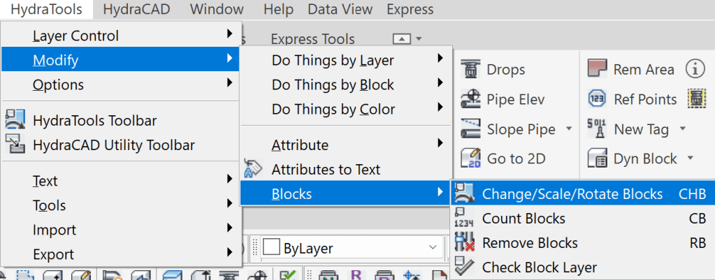
Step 3: Use the ChangeBlock command! It is found in HydraTools->Modify->Blocks->Change Blocks (or type CHB)
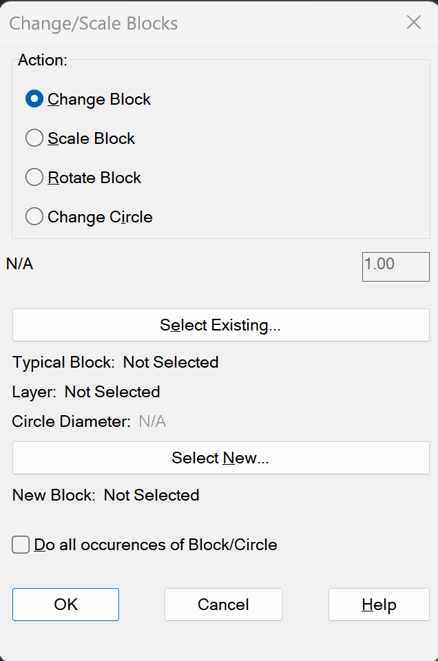
When that comes up,take a look at the dialog box. You can change blocks or circles using this tool:
For Blocks
Pick Select Existing and pick one of the existing heads. Then, pick Select New and grab one of the ew heads you inserted.
If you check Do All occurrences…, then all the existing heads of the same selected existing type will get converted. Do this once for each kind of head.
For Circles
Pick Change Circle. Pick Select Existing and pick one of the existing heads. Then, pick Select New and grab one of the new heads you inserted.
All circles matching the diameter and layer of the circle you selected will get converted. Do this once for each kind of head.
Step 5: Sometimes original blocks are not inserted with a ‘normal’ scale factor. This is pretty easy to notice. If, after you convert your heads, some or all of them need to be re-scaled, start this command again and select Scale Block. Pick Select Existing, like before. Then choose Do all occurrences… You will be prompted for a new scale factor. Enter this.
There are two overhauled commands in AutoCAD 2020 that are used pretty often; and that have changed considerably. One is the PURGE command, which I covered in an earlier post. The other is INSERT, which I will cover here.
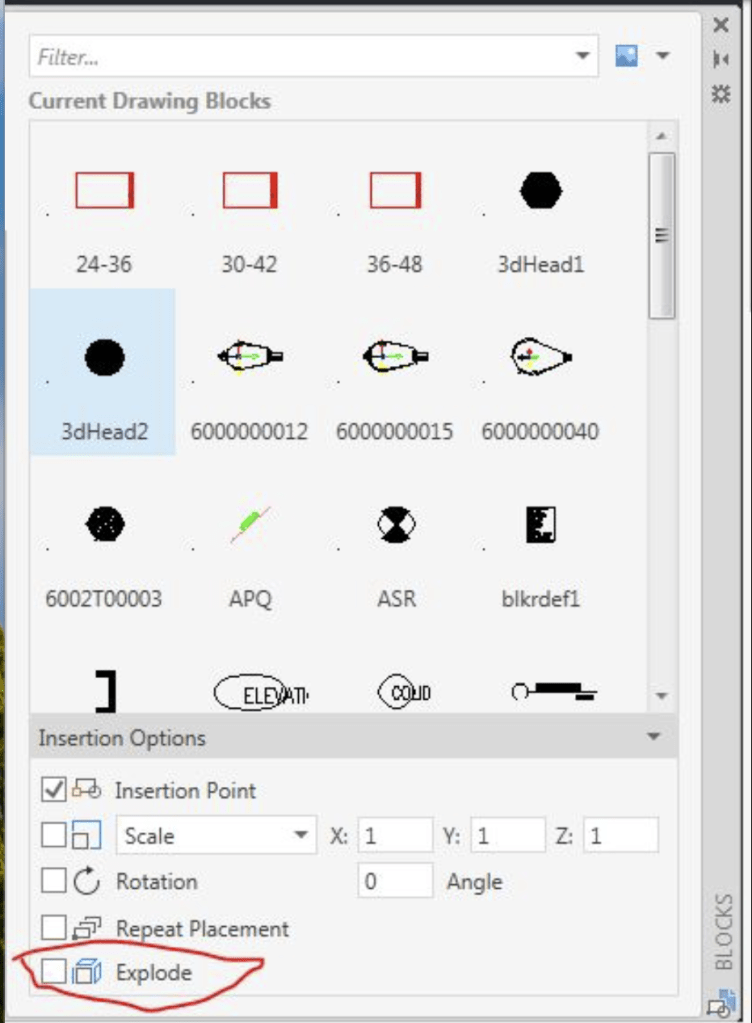
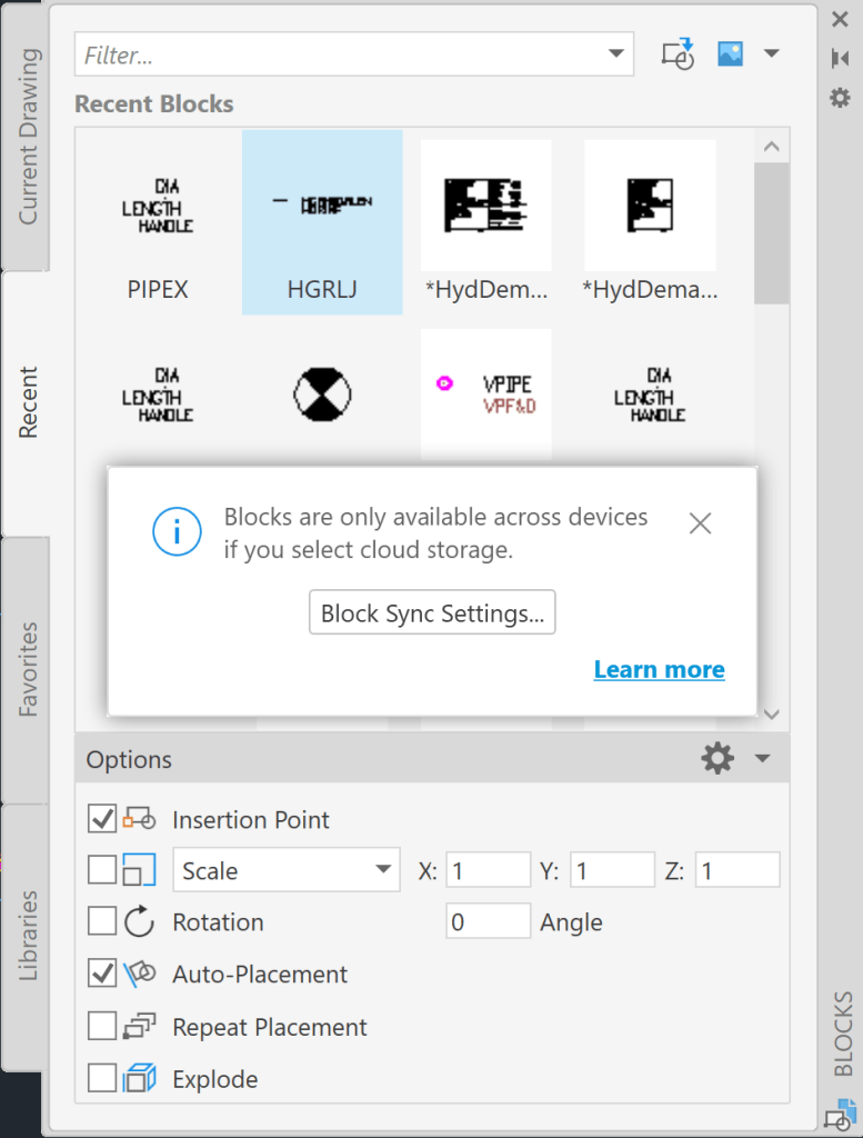
Insert has changed considerably, in that it is considerably more complicated. Typing it in yields an Insert palette:
The Current Drawing tab shows all the blocks currently defined in the drawing, whether or not they have been actually inserted. From this tab, you can pick or drag and drop the blocks into the drawing.
—
The Recent tab shows you the most recently inserted blocks, giving you a smaller list to choose from. however, this requires that you set up a cloud storage system to synch with. View the Help on this tab if you want to proceed
—
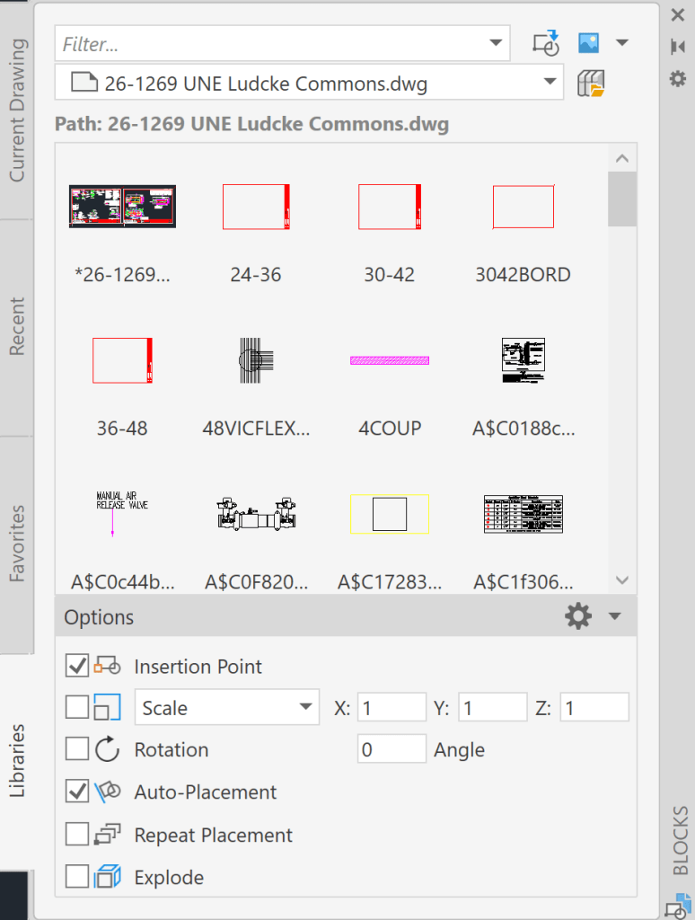
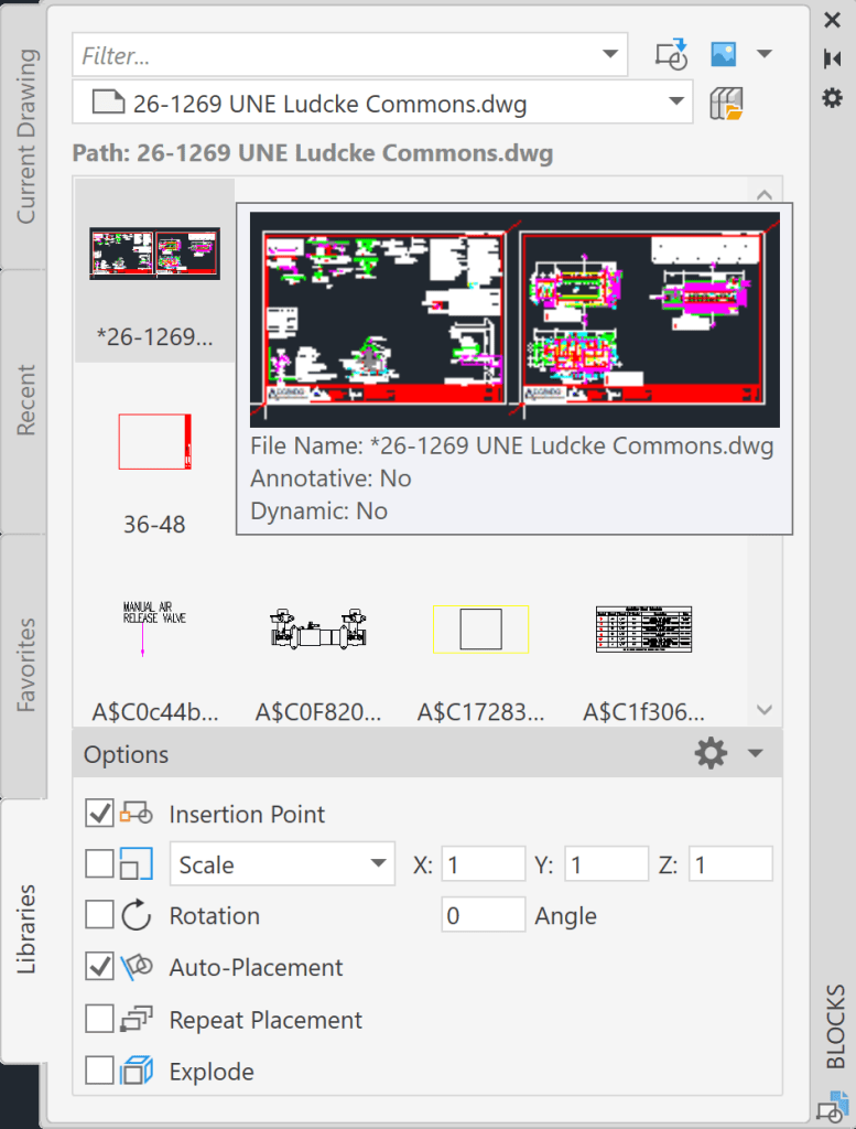
To insert a block from another drawing, however, select the Libraries tab. The first time you use this command, the Libraries tab will be blank with a note to the effect of Open Block Libraries.
Picking that, you will be asked to select a drawing to access, or, you can pick the Library Book symbol, below, for this same purpose:
Picking a drawing will display all of the blocks defined within that drawing. You can drag or drop these blocks into your drawing.
If you want to insert the entire drawing, such as in the case of a background to work off of, select the very first block in the upper left. This is the entire drawing. I suggest checking the Explode and Insertion Point boxes when inserting. I do not recommend the drag and drop feature for this, as the entire drawing has to get loaded in before you can ‘drop’ it where you want it
Finally, now that you have been forced to read all of this, if you want to use the good old Insert command from days of yore, simply type in CLASSICINSERT to do so!
Want to keep riser nipples from showing both center and cut length when plotting? Tried to freeze or turn off layers?
AutoCAD has a newish feature that will help you do just this. Its call VP Freeze for Viewport Freeze.
Open the Layer palette. Find the HPipesCGen layer. Click the Square Sun icon in the New VP Freeze column. This will freeze this layer in viewports!
This modification has been added to HydraCAD V56.04 and V55.05. A change made to HydraCAD templates and layer script so that the HPipesCGen layer is set to default this way.