The H-Factor

Reducing Entropy

Recent Posts

Adding Hanger Types to HydraLIST

If you want to use a new type of hanger, or are a fab shop that gets a job from a contractor that uses a hanger type that you do not have, it is easy to add that new hanger type to your own machine. A hanger is an assembly, and an assembly is just…

Welcome

Recently our previous blog service (Typepad) ended their business – so, we have a new home. It will take a bit to get images back and displaying properly, but we are working on it! Final pageview count of original Typepad blog: 387,232

Using a Non-Standard Pipe Type in HydraCALC

A customer called today asking how to enter a 1″ black plastic underground pipe for the calc. This particular situation sounded unique enough that I did not tell him to add that pipe type to our database, as I would have if he expected to see this pipe type used repeatedly. I told him to…

September 2026
M T W T F S S
 123456
78910111213
14151617181920
21222324252627
282930  
  • My coworker Bill wrote this up, based on frequent requests for help with Pressure Reducing Valves:

    There are two types of PRV valves, so there are two ways to handle the calculation:

    Type 1 – Fixed PRV

    Three calculations are required for a factory set or field adjustable PRV: Static at PRV, System Demand at PRV and Maximum Residual Pressure Available at PRV. Use those calculation results to determine which setting to use for the required flow demand.

    Two HydraCALC Input files are required for each of those three calculations: Input file 1 – The sprinkler system to the PRV and Input file 2 – the PRV to the supply.

    You can find a document for this named Fixed PRV Calculation.pdf in your \HES\HydraCALC\Ver50\Docs folder

    Type 2 – Auto-Adjusting PRV

    A Cla-Val – Pressure Reducing Valve (there are other brands available) will automatically reduce a higher inlet pressure to a steady lower downstream pressure, regardless of changing flow rate and/or varying inlet pressure. You will need the manufacturer’s material specification sheet for the valve you are using and enter the pressure loss for that valve.

    The pressure loss for this type of PRV can be entered into HydraCALC as a fixed pressure loss. You can find a document for this named Auto-Adjusting PRV Calculation.pdf in your \HES\HydraCALC\Ver50\Docs folder

    Note:

    If the PRV is located at a fire pump (Usually a Cla-Val type) the information can be entered into the HydraCALC pump curve. Enter the pressure limit (such as 175 psi max) and enter the PRV type and model in the “Regulated By” input field. The calculation process will take care of the PRV in the pump curve.

  • This idea is from long time customer and frequent good advice giver, Larry Howell at L & K Fire Protection in Marion, Illinois

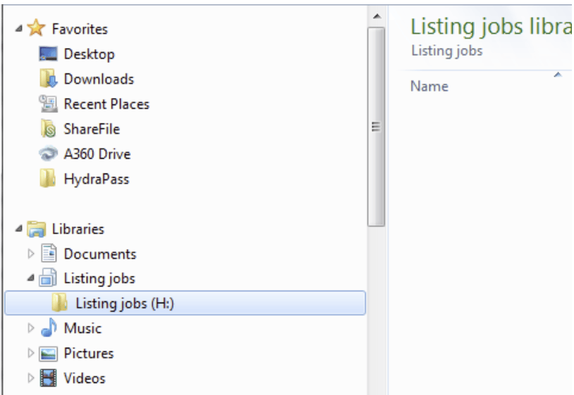
    “I wanted to share windows file explorer libraries with the blog users, as I just discovered their usefulness. When choosing a place to save calculations and stock listing files, the default does not work for us, finding the right directory on the server takes several clicks and looking. When choosing where to save the file, favorites do not appear but libraries do appear in the save options, if current job files are added to the libraries you can be only a couple clicks away. This would save more time with the more calculations and listings you have. This also saves us from moving files from our local “hes” folder to the proper directory for the project on the file server.”

    Using graphics to illustrate Larry’s suggestion, here is how to do this:

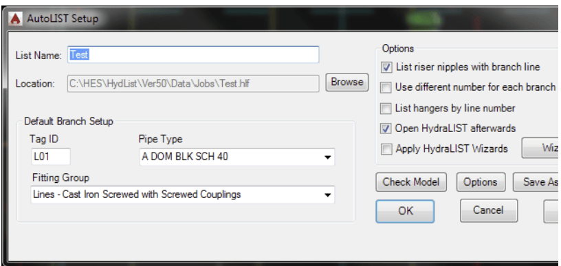
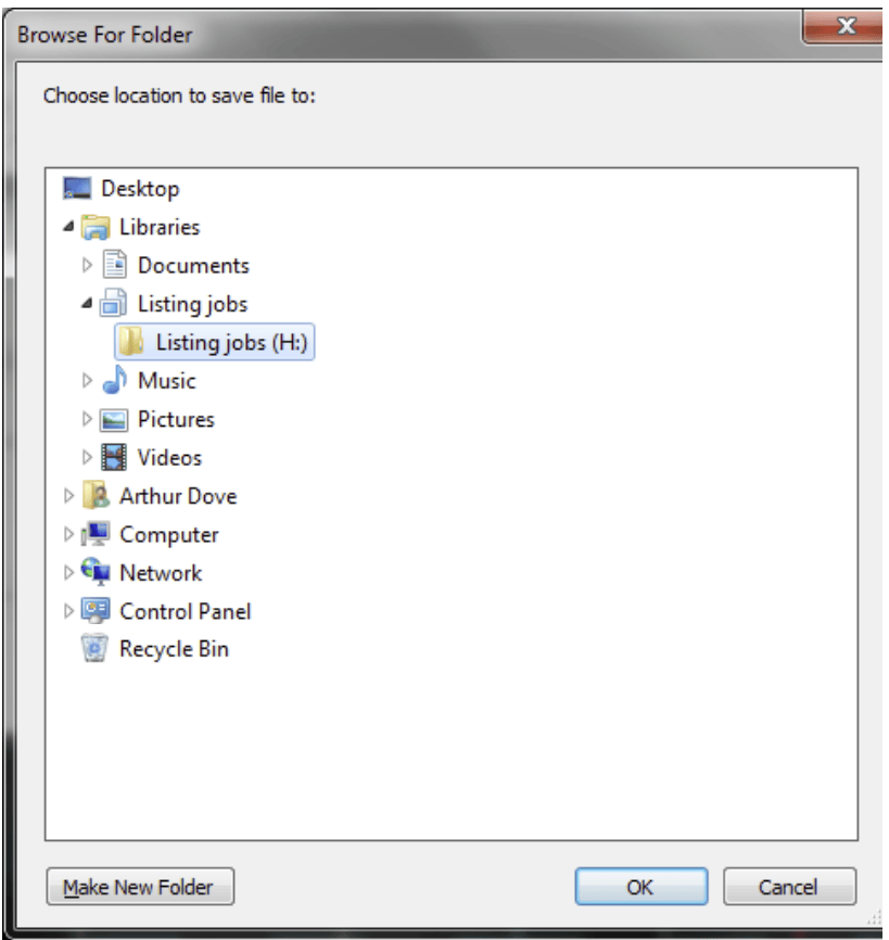
    Say that you, like Larry, want to write your listing (or calc) jobs to a location other than our default location. This is typically done by picking the Browse button and steering to the desired location:

    But… this can get tedious and tiring, especially if the location is buried deep in a path structure on a different drive.

    So,

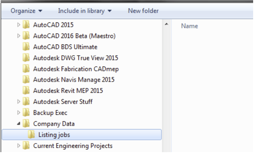
    1. Find the folder to be your Listing files location

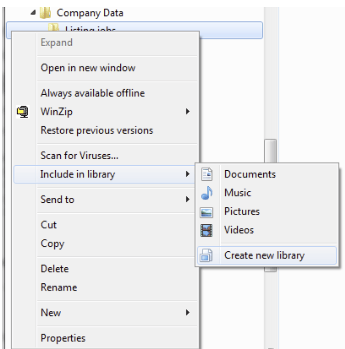
    2. Right-click on it, pick Include in library, then pick Create new library

    This will create a new Library with the same name as the folder you clicked on

    3. Now when you pick Browse in the Start AutoList (or Start AutoCalc) command, the folder you created is very easy to locate and select. The HydraLIST job will be created in that folder!

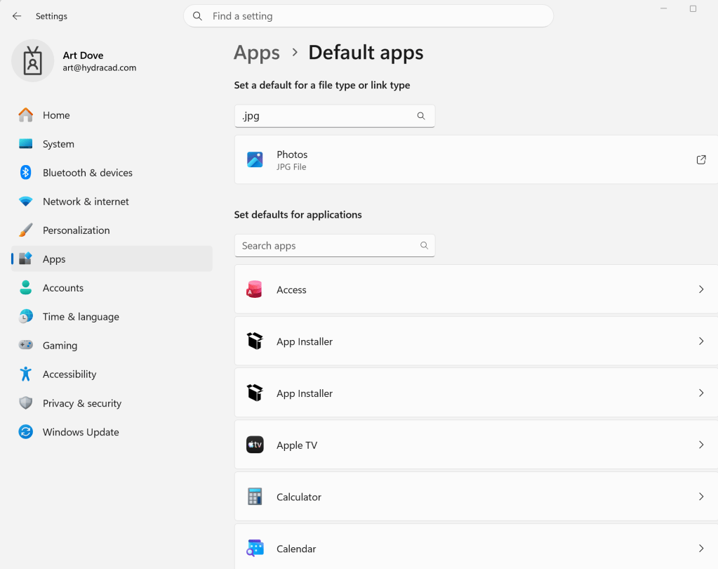
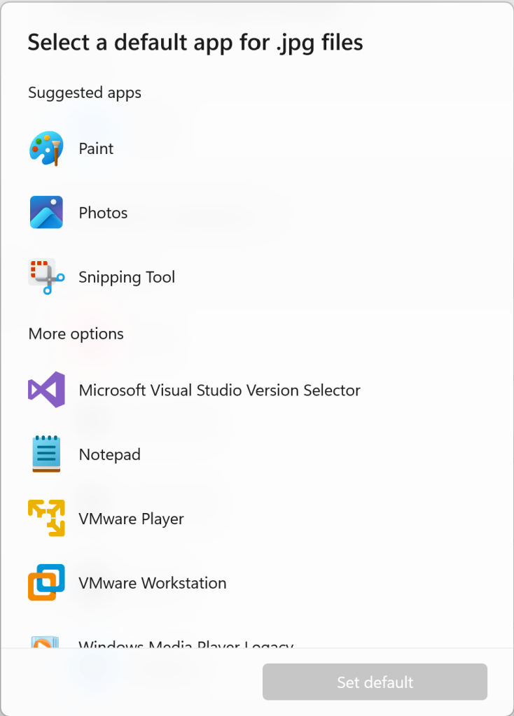
  • I had a customer contact me today because he was unable to use any of the internet spawning commands in HydraCAD including Send an Email to Hydratec, Hydratec Website and Hydratec Support Blog (this blog). The cause of his problem was that a browser was not associated with HTML files. Instead, some other program was.

    This can be fixed by tweaking the registry, but there is a more friendly, safer way to do it:

    1. Press the Windows Key + I to open Settings.
    2. Select Apps on the left menu, then click Default apps.
    3. Type the file extension (such as .jpg or .pdf) into the search bar at the top.
    4. Click the current app icon next to the file type and select your preferred program


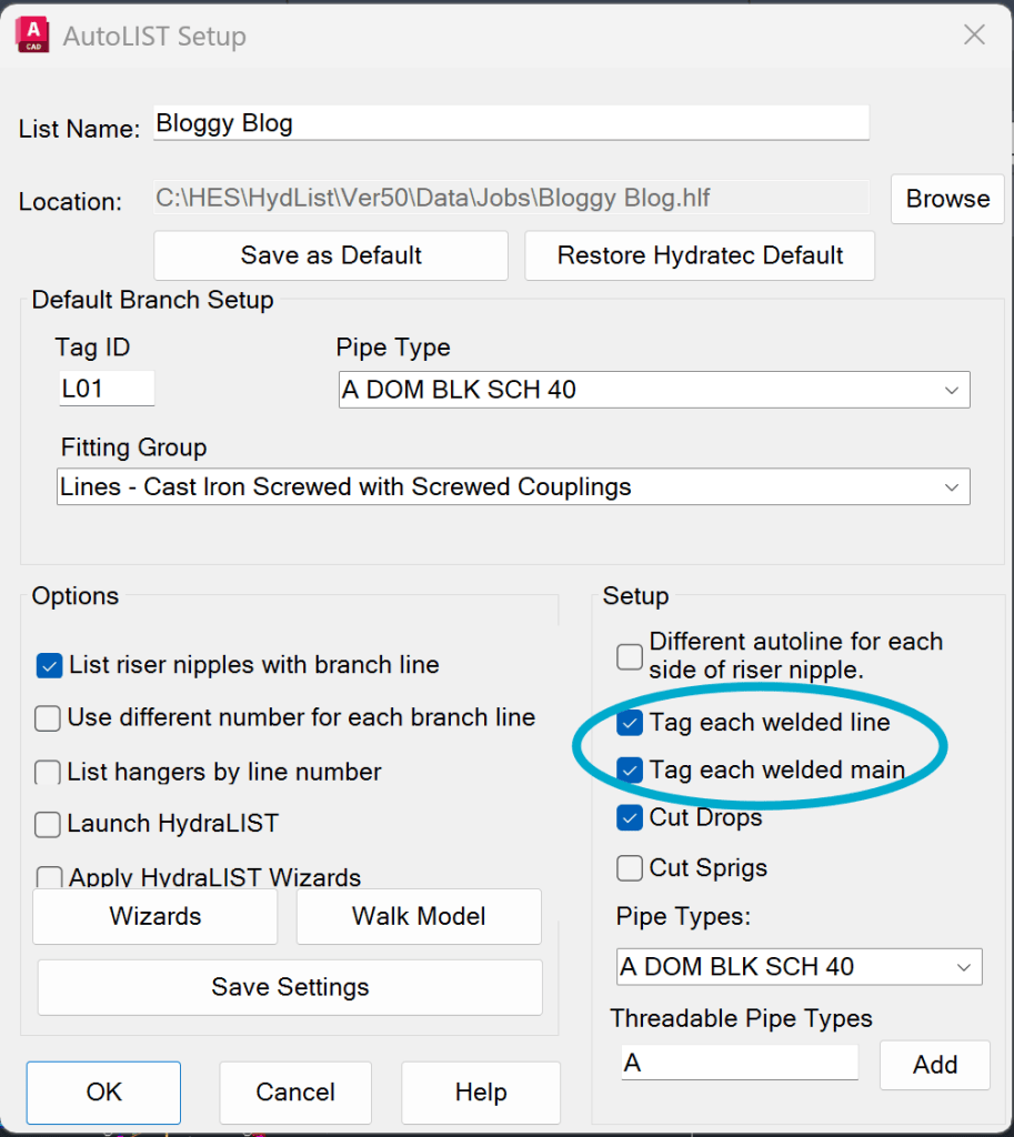
  • One of the best features in AutoList is the addition of automatic line and main tags. Where are the settings for adding these found?

    When you Start AutoList (SAL), right on that dialog:

    You will find two options pertaining to the tags, one for lines and one for mains. Select the ones you want to see and away you go. These settings are now stored on your computer for each subsequent job.

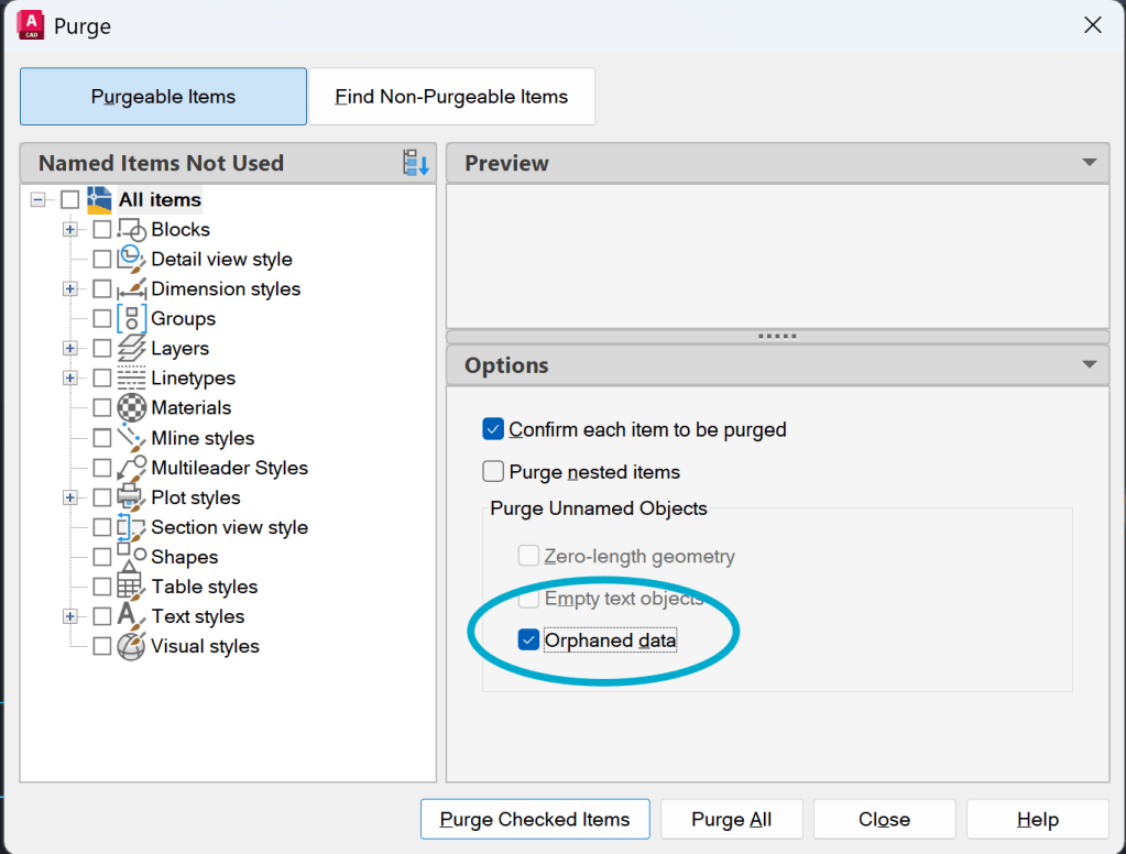
  • A customer contacted us about a problem with his drawing as the drawing only had about a hundred heads but was 32+ megs. It turns out that the drawing had a large number of DGN Linetypes, and these really bulked up the DWG file. Before we got to dig too deep into the problem, the customer contacted us again and told us that he discovered that AutoCAD has an option built into the PURGE command to eliminate these. The option is the ‘Automatically purge orphaned data’ option in the PURGE dialog.

    This reduced this particular drawing to less than one meg and prevents further problems with ‘junk’ data from DGN files from coming back as background details get copy and pasted into the drawing.

  • From a customer:

    “Hello.  I have used Hydratec for a number of years and believe it is the best and easiest software to use.  I do have a suggestion.  Is it possible to put a drop-down on the beginning of Hydra-Calc Setup along with the head area, first node, etc. that would allow you to choose the C-Factor of the lines and mains?  When calculating dry system, currently you have to choose each line to change the C-Factor.  I think adding this would make calculating dry systems easier and faster.”

    There is a faster way to do this already. It is especially useful since many authorities now insist that even galvanized piping be calculated using a C-Factor of 100.

    There have long been two pipe types that are set up with a default C-Factor of 100. The idea is to select these pipe types when AutoCalculating (or manual calculating). You will then maybe only need to change the riser pipe to C=120.

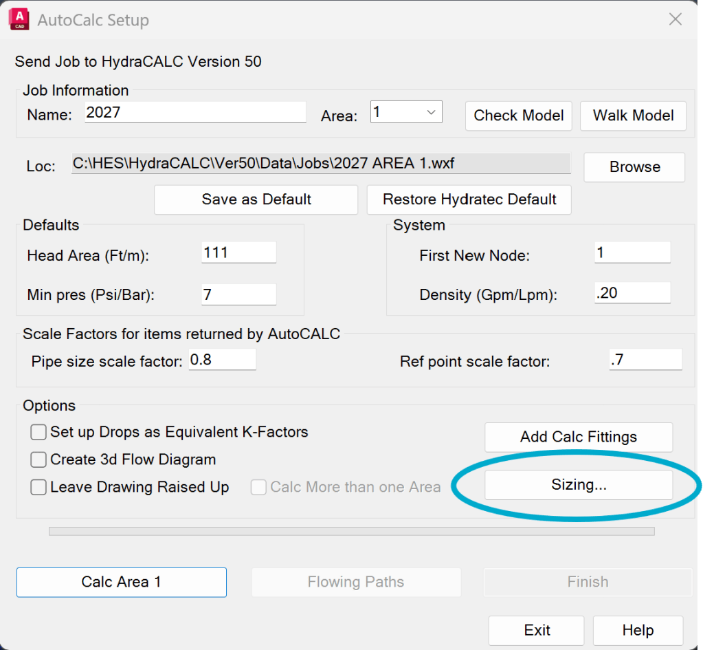
    When you pick start AutoCalc, it brings up a dialog. Pick the Sizing button.

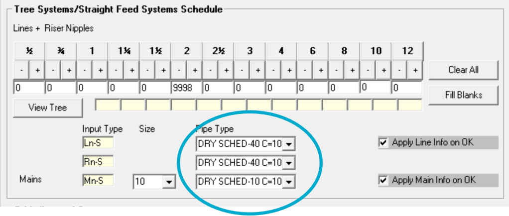
    This brings up the Sizing Schedule. Pick the dry pipe types you want for your branchlines, riser nipples and mains.
    Note that there are currently four dry pipe tables:

    DRY SCHED-40 C=100
    DRY SCHED-40 C=120

    DRY SCHED-10 C=100
    DRY SCHED-10 C=120

    Pick Ok and these will be used for your calculation and are now the defaults for the next calc as well.

  • From a longtime customer:

    Q: What do you think about having the option to do arms as an option for pretty pipes, example why; I have an existing system and the lines and mains are existing and the arms are new so I want the pretty pipes of the existing to be blue dashed and the arms to be red solid?

    A: We will indeed consider a separate item for Pretty Pipes, but there are two options right now:

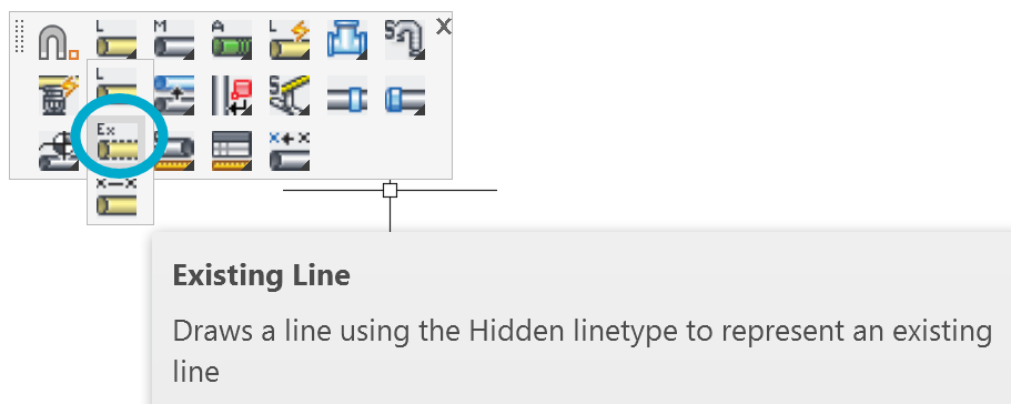
    1. Pretty Pipes already produces polylines that exactly match the linetype of the piping drawn! So, you can use the Existing Line and Existing Main command to draw the mains and lines using the HIDDEN linetype. These will then be Pretty Piped using the same (HIDDEN) linetype when that command is run.

    Note: be sure to select the regular Line or Main command when done drawing existing piping, in order to reset the linetype to ByLayer (CONTINUOUS). Conversely, you could simply change the linetype using the AutoCAD option for that command:

    -OR-

    2. HydraCAD has long had a command called Change item Colors. It is found right after Pretty Pipes on the Cleanup toolbar. What does it do? It lets you assign colors to different parts of your drawing. It is run after you run Pretty Pipes, hence it’s location on that toolbar.

    You can assign three additional colors to Pretty Pipes such as Existing Pipe, Demo Pipe and New Pipe. You can also assign different linetypes to these parts of the drawing as well. The colors and linetypes can be applied to the areas you select or to just one pipe if you want. Sprinkler heads and other objects will change color as well.

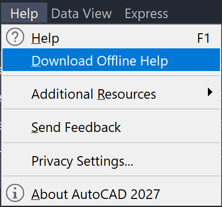
  • I really, really don’t like the way AutoCAD accesses its help on-line instead of on my local drive. The time lag drives me nuts and if I am away from the internets, I cannot use it, period. Luckily, Autodesk has made it easier than in the last few versions to download and install the offline help!

    Pick the Help pulldown and then pick Download Offline Help. After that is downloaded, go ahead an locate the download and install it


  • From a customer today:

    Where do you change the standard length for a piece of pipe so optimization will work for 20’-0” pieces. We are doing a stainless job.

    Here is how…

    Open HydraLIST and pick the General Data button, below:

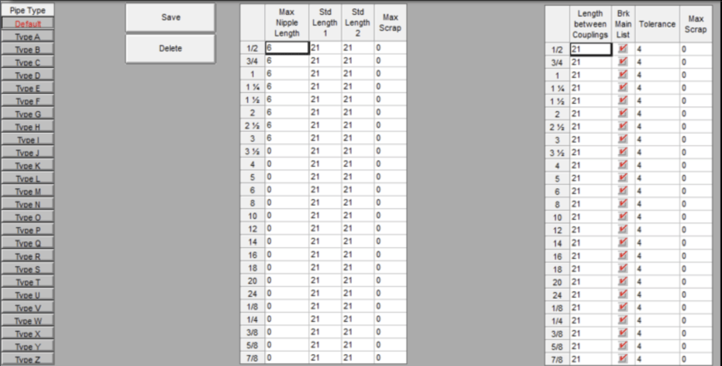
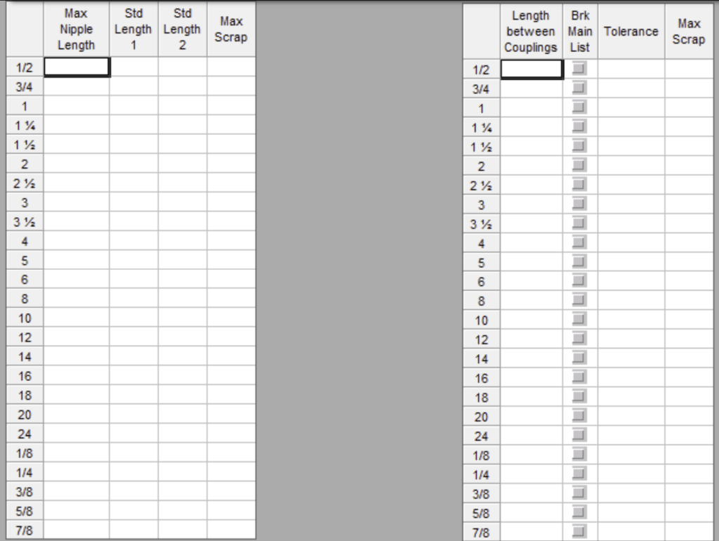
    Pick the Pipe Length Tables tab. On the left, you will notice 27 pipe types. ‘Default’ is the only one shipped with HydraLIST. It is preset for 21 foot lengths of pipe. The other 26 alphabetical choices are used to record specific lengths for a particular pipe type.

    Pick the red Default button to fill out the tables with the current settings:

    If you want to change the Default length to say, 25′, then enter 25 in all the fields that currently have 21. Pick Save to record those changes, then pick the Project Data button (same icon as the General Datas button) to go back to HydraLIST Input:

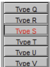
    If, however, you want to create a set of pipe lengths for a particular pipe type (in this case, Type S for Stainless), then pick the letter of the Type you want to work on.

    This will show an empty table if the type has not been previously filled out:

    Enter the particulars for this pipe type. Stainless usually comes in lengths of 20′, so we would enter 20 in the Std Length 1, Std Length 2 and Length Between Couplings columns for all sizes.

    Some other entries in these tables:

    Max Nipple Length –  the longest length that can be considered a nipple. A part number is required to be set up for all lengths up to this length

    Max Scrap – the longest piece conidered to be scrap

    Brk Main List – Check this box for each size to force a break in the pipe at the Length Between Couplings (LBC) distance. This is the usual condition for most users. Basically it means that if you enter a pipe longer than the LBC distance, it will be automatically broken in the stock list and a coupling added. If listing from the drawing, this never comes in to play unless to neglect to cut couplings in and/or cut them in at a length longer than the LBC.

    Tolerance – The main will only be broken if the pipe length exceeds the LBC plus the tolerance

    Again, pick the Save button and then the Project Data button when finished.

  • The CPVC command on the Listing toolbar very quickly generates a raw material list for plastic, but can be used for just about any other piping material. And, it creates a file that can be imported into HydraLIST to check for availability of fittings and swapping of bushings for other fittings.

    Once selected, you get a dialog box:

    The program automatically filters out pipes size larger than the setting seen in the Largest diameter of CPVC item. I pick OK on the following drawing and select what I want to list:

    And I get a list, within seconds:

    You could edit this notepad document for any changes you might like to make, and print it for the shop. Or, you could import it in HydraLIST and check to see which fittings are in your database and make changes there.

    Open HydraLIST and save a new job – ie. CPVC Test. Switch to the Miscellaneous tab and enter a new Section ID named CPVC (exact name unimportant). Pick Load List. You will see LastCPVCList.itf in the list. Select it and pick OPEN.

    This loads the most recent list created by the CPVC list program:

    Pick the Error Check Section button. This will search the database and flag parts that, although they may be manufactured, are not likely to be used, and therefore are not in your database:

    Note these are usually crosses or reducing fittings that most companies do not stock because they prefer the use of straight fittings and bushings. I will replace the three different reducing crosses with a 2″ straight cross and add bushings. I click on the first open line of the list and pick CPVC Fittings from the left and pick Find. This adds all the available fittings:

    I locate 2″ CPVC CROSS and put in a quantity of 10 (the sum of the three reducing crosses being replaced). I also locate the bushings and put a quantity of 16 next to the 2 X 1 CPVC BUSHING and 5 next to the 2 X 1-1/4 CPVC BUSHING. I also find the 1-1/4″ CPVC 90 ELL and enter 1 for that and 1 for a 1-1/4 X 1 CPVC BUSHING. I then pick the Clean Up button to add those to the list.

    Lastly, I click on each of the replaced fittings and pick Delete to clear them. This gives you a list you can then process and hand to the shop!