The H-Factor

Reducing Entropy

Recent Posts

Adding Hanger Types to HydraLIST

If you want to use a new type of hanger, or are a fab shop that gets a job from a contractor that uses a hanger type that you do not have, it is easy to add that new hanger type to your own machine. A hanger is an assembly, and an assembly is just…

Welcome

Recently our previous blog service (Typepad) ended their business – so, we have a new home. It will take a bit to get images back and displaying properly, but we are working on it! Final pageview count of original Typepad blog: 387,232

Using a Non-Standard Pipe Type in HydraCALC

A customer called today asking how to enter a 1″ black plastic underground pipe for the calc. This particular situation sounded unique enough that I did not tell him to add that pipe type to our database, as I would have if he expected to see this pipe type used repeatedly. I told him to…

September 2026
M T W T F S S
 123456
78910111213
14151617181920
21222324252627
282930  
  • Grips, IMHO, are the best thing AutoCAD ever added to their program. When they first came out, everyone freaked out (myself included) and we turned them off until we got a better, um, grip on them.

    Many (most?) people use grips to move a single object. But, they can be handy to use many objects at once, too.

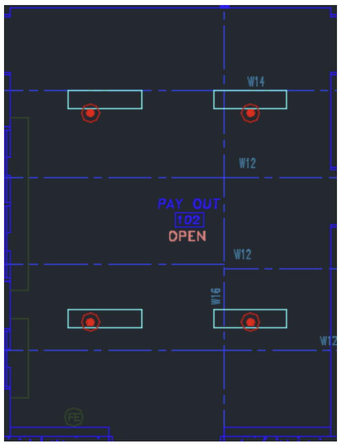
    Look at the image below. All four heads are amongst lights, and I want to move them all down 16 inches:

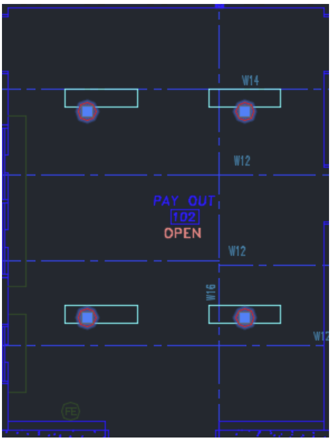
    Pick each item to highlight it:

    Now, hold the SHIFT key down and select each of the four grips, then release the SHIFT key:

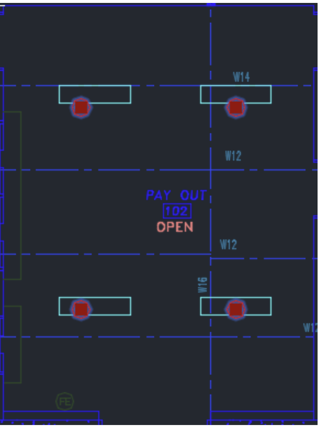
    This makes each grip be a ‘hot’ grip. You can now pick any one of them to move all four items at once:

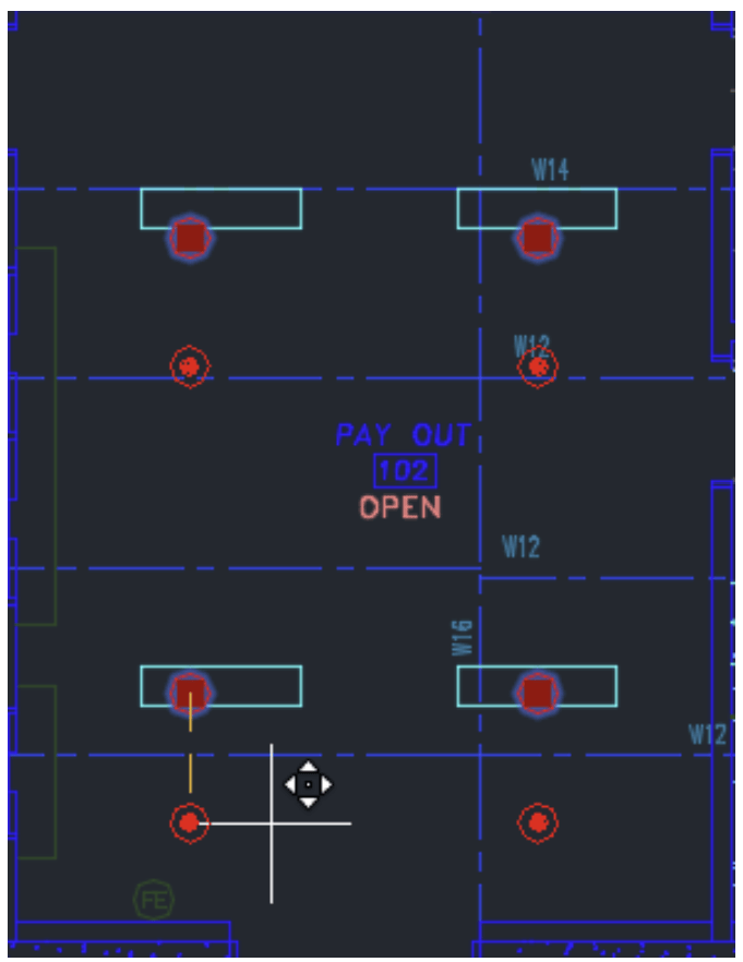
    Wih ORTHO on, I point down and type in 16 and press enter to move the heads that distance

    Try it out!

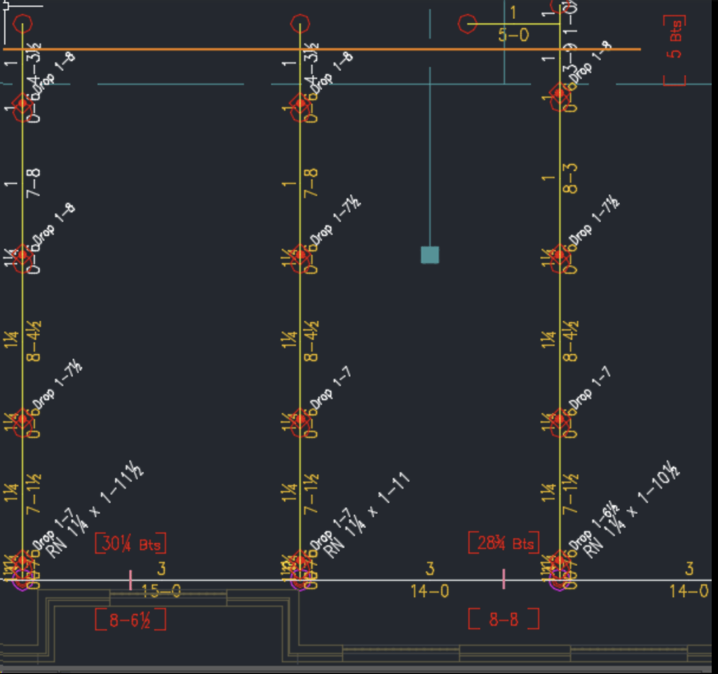
  • From a Customer: “On this job, the main is sloping (using the sloping pipe block), as are the lines. I need the last head to be 5” down from the deck. I Gave them a fixed elevation of [5 Bts] and a fixed elevation at the top of the riser, [34 BTS], but it does not work properly.”

    The solution here calls for using Above Finished Floor (AFF) blocks. Why? Because the sloping pipe markers cannot use a BTS as a starting elevation – it has to be an AFF. Fortunately, there is an easy way to do this.

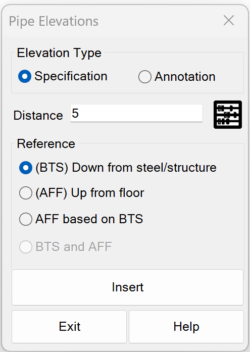
    In the Define Pipe Elevations tool (AFF) there is an option named AFF based on BTS. This tool will automatically calculate the AFF at the point selected, adding both an AFF block and a BTS block.

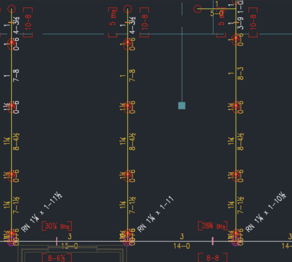
    If i input the 5 inches as the Distance, select AFF based on BTS and then select Pick Defining Points, I can then pick near the last head, as requested by the customer.

    As this requires a single insertion point, it can only be inserted on one line at a time. You can, however, stretch the orange definition line across as many lines as you like. Or, you can copy or array the blocks as needed, as long as the elevations line up.

  • From a customer: “When I mirror typical piping for an area, how can I get the riser nipples to rotate properly without having to reinsert them all?”

    This is from the drawing he sent me:

    There is a solution. And, the truth is, I didn’t know about the following tool myself.

    1. Pick the 3D Modeling Options command (3MO) to open the SMaRTools Options dialog

    2. Then, pick the HydraPipe Setting tab

    3. Pick the Change All RN Symbol Rotations button. This opens another dialog box:

    4. For the example above, I chose Rotate By Process as my option and picked Proceed. I then pick four riser nipples and pressed <Enter>

    Each riser nipple is the rotated to match the pipes it is connected to. Problem solved!

    Note: To rotate the riser nipple text, use the Rotate Riser Text (RRT) command in the Cleanup Sizes toolkit.


  • You likely know that Ceiling Heights and Drop/Sprig Lengths are inserted using the same tool, but here is a list of some things you might not know about this tool:

    1. If you are manually specifying the drop lengths, then use the User Specified setting under Length Determination. If you want the computer to figure out your drop lengths, then choose the Computer Gen. setting. You will notice that the text above the elevation entry box changes based on that setting.

    2. Only sprinkler heads that are configured to be 'On a Drop' or 'On a Sprig' pay attention to this dialog box and its resulting definition windows

    3. Drop Lengths/Ceiling Heights that result due to the use of this command are further adjusted by takeouts applied by the AutoList routine for the fitting it is attached to and by the Head Adjustment setting in the Select Sprinkler dialog box

    4. If all of your drops are the same length, it is easiest to make one big window around your entire drawing. Don't worry if upright heads get caught up in this window. See Rule 2, above

    5. If most of your drops are the same length, it is still easiest to make one big window around the entirety of the drawing. Then, draw smaller windows around those heads that have a different length. The easy to remember rule is that the 'smallest window wins'

    6. The drop windows do not have to perfectly line up with the walls of the rooms, the only important thing is that the heads are completely within the associated window

    7. Drop lengths are recalculated and redisplayed every time you elevate the drawing, and return it to 2D

    8. You have a lot of control over the drop tags that appear when you elevate the drawing. Pick the Annotation Options button to get to the annotation setting screen:

    Here, you can control the height and angle, plus the wording of the tags. If you don't want any tage, you have that option as well.

    9. The definition windows are in is a layer (DeflinesCeiling) that is set to not plot, to reduce clutter on the drawing. The Ceiling Height blocks will plot, as will the drop/sprig text that appears when you go to 3D


  • Most people seem to know that holding down the ALT key while tapping the TAB key switches Windows applications, not as many appear to know that holding down the CTRL key while tapping the TAB key cycles through open Documents or Drawings _within_ the current window. In other words, if you are in AutoCAD, and have more than one drawing open, holding down the CTRL key while tapping the TAB key will cylce through the drawings you have open.

    Bonus tip – If you have a Windows key on your keyboard, holding down the Windows key and pressing E opens up Windows Explorer. Windows+I opens Internet Explorer, Windows+D displays the Desktop. A complete list of Windows key shortcuts can be found here: Windows Key Shortcuts

  • These four commands really make it easy to modify drawings. Move Main and Move Line have different options, but Erase Main and Erase Line work the same as each other.

    Move Main

    Move Main can be used to move your main over just a little, or over a lot. It can even be used to move the main to the other side of a head. I will do that with the main below, which is zoomed in for clarity.

    I pick Move Main and am given the following options:

    Coupling Segment will ask you to select the main pipe, and will find the pipe between the nearest couplings. Only that segment will be used. Straight pipe run will move all main pipe in the same orientation as the pipe selected. If the main changes direction, it will be selected only up to that point. You can pick the shaded option with the mouse, type in the colored letter, or right-click or press Enter to get the Straight option, which is the one I am doing, here.

    I pick the main and am then given two options, below. I can just pick a point on the screen to plop the main down, or I can right-click to choose the Direction then Distance option, which I do

    I am then asked to pick a point to show which side the main is being moved to (kind of like the Offset command). I pick 'north' of the main. Distance is not (yet) important

    Then, I enter the distance. I choose to type in 12' and press Enter. The main is then moved:

    Move Line

    I want to move this line over to the left one foot

     Move Line gives you three options, below. The first does an entire straight run of branch line, the second does one side, and the last does the same as the Move Main Coupling segment


    If I pick Straight pipe run by clicking on it or right-clicking, I am asked to pick a line, which I do:

    Then, just like the Move Main command, I pick the line and am asked to just pick a point on the screen to plop the line down, or I can right-click to choose the Direction then Distance option, which I do

    I am then asked to pick a point to show which side the line is being moved to (kind of like the Offset command). I pick one side of the line. Distance is not (yet) important

    I then put in a distance of 12

    A question unique to Move Line is whether the heads should be moved with the line, or left where they are. The default is to not move them (No), and that is what I go with

    The branch line is moved and armovers the the heads are created in the proper layer!

    Note: Moving the line back 12 inches would remove the armovers

    Erase Main and Erase Line

    These two commands work essentially the same way as each other, with the additional option of One Direction (explained above) for the Erase Line command

    Picking the main removes it, and the connecting riser nipples:

    Erasing a line leaves the main and removes the riser nipple (if present) and reconnects the main


  • Sometime back, I don't know when (between AutoCAD 2010 and AutoCAD 2013), AutoCAD altered the command line so that you can select the option on commands instead of typing it in. To see what I mean, type in ARRAY at the command line to see an example. Select any drawing entity and press enter. The following comes up:

    Notice that the Rectangular, PAth and POlar options are grey-lighted. This means you can simply click on them to select them, instead of typing in the blue letter code or pressing <Enter> to get the default.

    Keep that in mind the next time you are asked for an option from the command line.

    PS – If you like the old-style ARRAY command, read this: Missing the Old School ARRAY Command?

  • The Lay Out Hangers command came about because one of my coworkers suggested that it would be cool if a hanger command existed that acted like Main Couplings. Why? Well, Main Coupling will allow you to pick a welded line to visualize where the couplings will go before they are inserted, and it will offset the couplings so that they don't get too close to the heads. Substitute hangers for couplings and you see why this idea came about.

    So, we have the situation below. The designer wants to put a hanger on that first piece of steel, then every 15' thereafter (third piece of steel, here). The entire branch line has been cropped for brevity.

    Pick Lay Out Hangers

    This displays the dialog box:

    I set Hanger Distance to 15' and outlet offset to 6". If we knew what the distance to the first piece of steel was, we would use that as the entry for First Hanger at:. Instead, we can select the distance from the drawing itself. Notice, also, that adjustments can be made for sloping pipe, although that is not necessary, here.

    Pick the Pick It < button next to the First Hanger at: entry field. Then, pick the main, then the first piece of steel. The NEArest osnap is great for the first pick (on the main) and PERpendicular is great as a second onsap (on the steel)

    In my case this yields a distance of 2'5 7/8"

    Pick OK. Pick near the end the pipe to be hung (hint: no need to pick exactly on the end, just near it). In this case, it is the short takout piece. Then, zoom out so that all of the line is on the screen, or at least as much as you want hung.

    When you use this, you will see green plines and possibly red ones. The green ones indicate that the hangers will be inserted at the distance specified in the Hanger Distance entry field. The red ones indicate that the hangers would fall within the Outlet Offset distance of a head (here, 6").


  • RapidRefs has been around for a while, previously as its own command with its own button and everything. It is now integrated into the Reference Point command as an option.

    What's it for? It excels at labeling ref points at the top and bottom of multiple riser nipples, as in those present along a main connecting many branch lines.

    Look at this example:

    RR1

    I want reference points at the top and bottom of each riser nipple along that main. I want the tops to be labeled T1 – T8 and the bottoms to be labeled B1 – B8, starting from the right and going left.

    Pick the Reference Point command. Select the Rapid reference points option and pick Insert.

    Now, set the dialog box up as seen below. Notice the T and B as prefixes and the 1 and 1 as the starting IDs for the ref points. Also, this option is selected to insert ref points wherever riser nipples that connect Lines + Mains are found. Select the left arrow to indicate that you want the numbering to proceed in that direction.

    RR2

    Pick OK and select a window around the riser nipples you want to add them to. This will insert reference points at the top and bottom of each of the eight riser nipples on my drawing.

    RR3

    Notice that there are other options to allow you to fine tune the usage of this tool.


  • If you have an industrial park with a common undergound loop, or many floors in a building with piping out to a pump house, or any need to reuse supply piping, then the Open Append option in HydraCALC is for you. It will add the file you select to the job you currently have open.

    Build some supply piping to use on multiple calcs (below) and save it as usual.

    Then you can simply append it to the bottom of your current job by postioning the cursor in the line where you want the supply piping and picking Open Append off the File pull down menu. Then, select the file containing the piping you want to append.

    The piping will be inserted starting at the cursor location and continuing down for as many lines as necessary.