If you want to use a new type of hanger, or are a fab shop that gets a job from a contractor that uses a hanger type that you do not have, it is easy to add that new hanger type to your own machine. A hanger is an assembly, and an assembly is just…
Recently our previous blog service (Typepad) ended their business – so, we have a new home. It will take a bit to get images back and displaying properly, but we are working on it! Final pageview count of original Typepad blog: 387,232
A customer called today asking how to enter a 1″ black plastic underground pipe for the calc. This particular situation sounded unique enough that I did not tell him to add that pipe type to our database, as I would have if he expected to see this pipe type used repeatedly. I told him to…
How does AutoList decide what order to list piping in?
Here are the general listing rules that pertain to the order:
Welded piping (whether lines or mains) lists before Threaded piping
Welded piping is listed in alphanumeric order (specifically, the ASCII order)
Per the ASCII order, numbers list before letters. Punctuation marks, including spaces “ “ list before either (because spaces come before numbers in the ASCII chart).
You want the mains to list first, then the welded lines and then the riser nipples.
Label accordingly using this scheme:
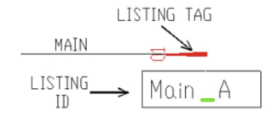
Label the Mains as such “ A”, “ B”, “ C” etc. notice the SPACE before each letter in those three examples. This forces the mains to list first.
Label the welded lines using a letter before a number, such as “L1”, “L2”, “L3”, etc.
Label the riser nipples using a letter before a number, ensuring the letter(s) used come after the letters used on the welded lines (RN comes after L), such as “RN1”, “RN2”, “RN3”, etc.
From the manual:
“Tagged welded piping always lists before tagged threaded piping. Within either type of fabrication, the naming of the tag further determines the order of listing. Numbered tags list before lettered tags. Lower numbered tags list before higher numbered ones (1 before 2). Likewise, lower lettered tags list before higher lettered ones (A before B). A space before a letter or number will make that tag take precedence over all others. A general rule worth following is to name the mains the lowest, the riser nipples higher and the lines the highest. Always use a space before a main identifier, and you shouldn’t have any problems.”
I will soon be posting about what rules apply to listing in general, as the order is only part of it….
We’ve all seen this. You have a nice drawing in front of you, but when you do Zoom Extents (or Zoom All), your drawing disappears and you find yourself floating out somewhere near the (ex)planet Pluto. You select all around outside of what you want to see and there is nothing there.
Sometimes you can zoom around out there and find a stray object and just delete and all is fine. Other times you can copy the ‘good’ stuff and paste it to another drawing. But what if that fails? The stray objects in question could be damaged entities, or text objects with null text, or blocks with nothing in them.
I had a customer send me such a drawing and after decades of just dealing with it, I wanted to dig deeper. I tried a suggestion whereas you do a Zoom Extents (ZE is one of our aliases) and then hit CTRL+A. This highlights everything in the drawing. The idea here is that you can then see more easily those things out in space, because they have an easy to see grip attached. This didn’t work for me.
So I found another video with the right suggestion (from Autodesk no less), for me, for this drawing. This is the link: Erase Empty Objects in AutoCAD
This is what it says to do:
Type in ERASE
Hit CTRL+A to select everything in the current space of the drawing, seen and unseen
Holding down the SHIFT button, grab what you want to keep. This will remove them from the selection set Erase will act upon. The remaining objects may or may not be visible
Press Enter
In my drawing, out of 80,000 objects, 12 were erased. A subsequent Zoom Extents now worked perfectly.
HydraCAD has long been able to create a file that can be opened in the JCI/Tyco/SprinkCAD Fluid Delivery Time program. That program is required to open the exported file. Hydratec and SprinkCAD worked together to offer this tool.
The file can be created from HydraCAD using a process similar to AutoCalc. The following is from the HydraCAD manual and the HydraCAD Help file:
Note: The pipe to be exported must be sized. There must be a water supply, at least one flowing head tagged using the Operating Sprinklers command. The drawing should be raised to 3D before executing.
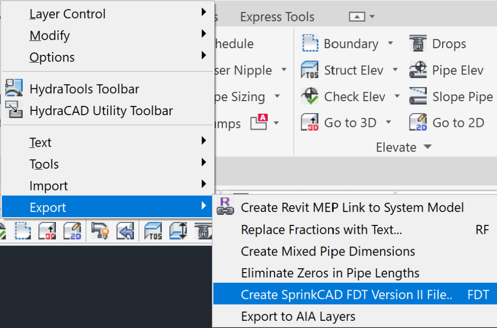
1. The menu command Create Tyco FDT File will create a file that can be opened and calculated in SprinkCALC with the FDT option. Select the command from the HydraTools->Tools->Export menu:
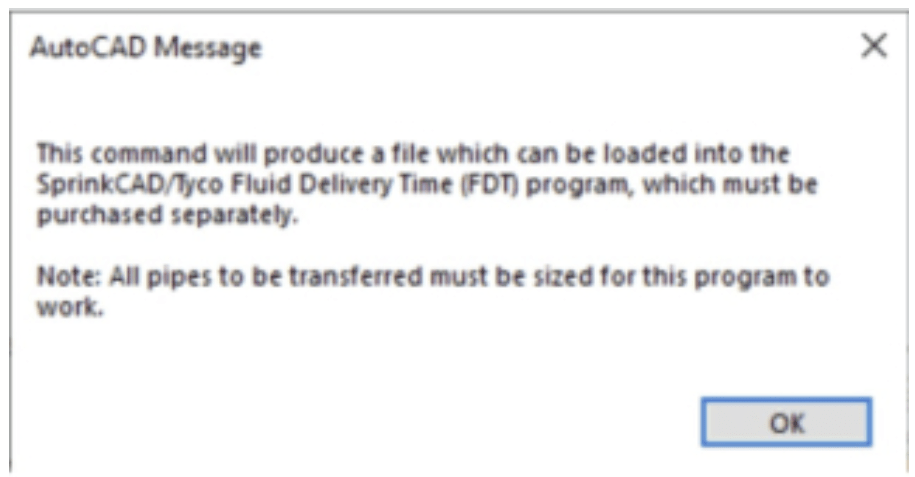
2. An informational message is displayed after launching. Press OK:
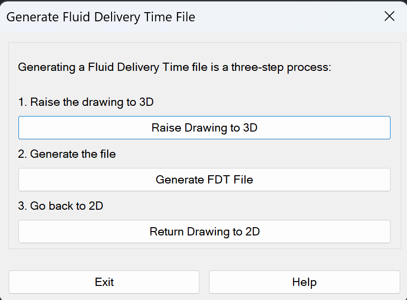
3. The below dialog box appears. If the drawing is not already elevated to 3D, pick 1. Raise Drawing to 3D. You will need to restart this command after the drawing is raised in this manner. If the drawing is already raised, pick 2. Generate FDT File:
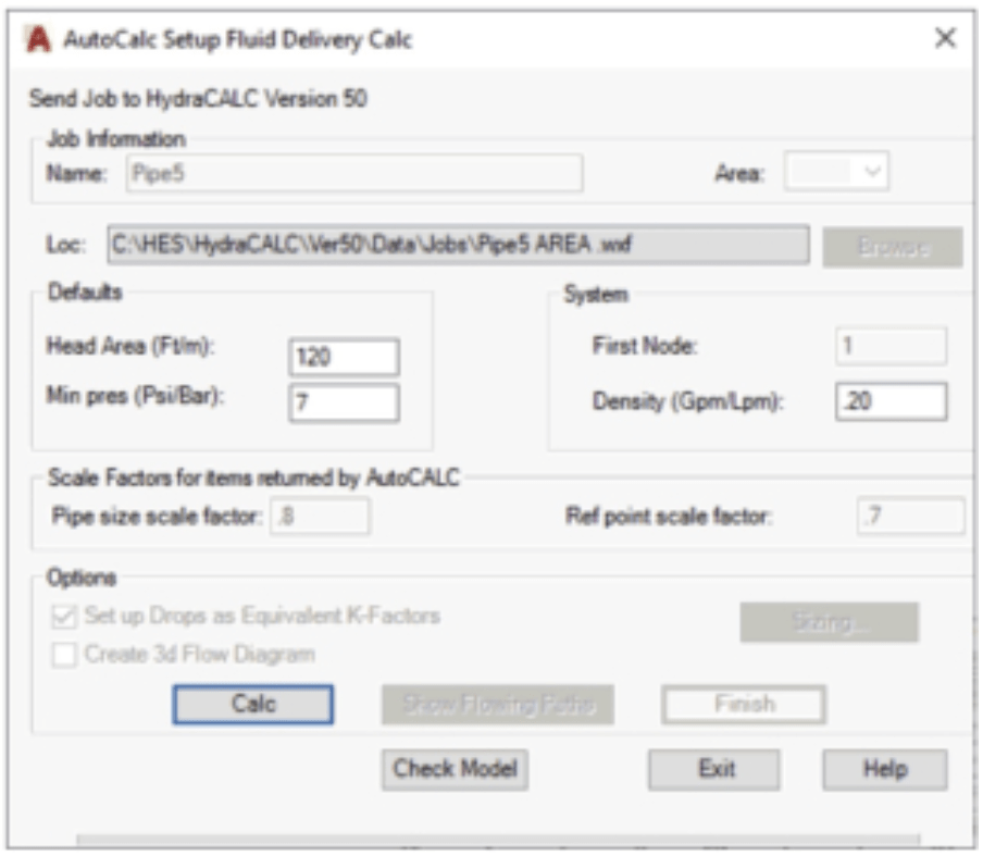
4. This displays the AutoCalc Setup FDT dialog. None of the settings here affect this particular process, so just pick the Calc button:
If you get an error message, the most probable cause is un-sized pipes. You can cancel the process and size them; otherwise, proceed and fix those pipes in the Tyco program.
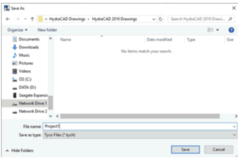
5. If there are no errors, the Save As dialog box will appear. Choose a location and give the file a name. The file will have the tych extension:
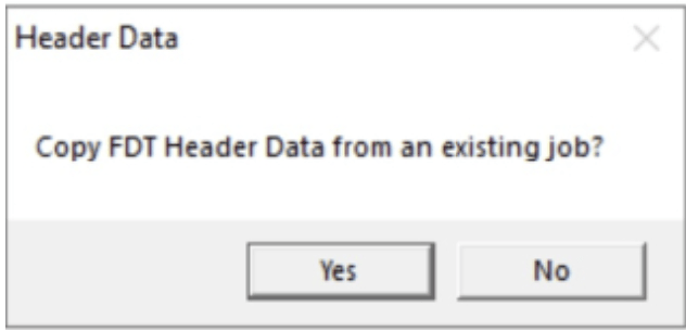
6. You will get a message stating that you are creating a new file and are given the opportunity to copy the header data from a file you have already created.
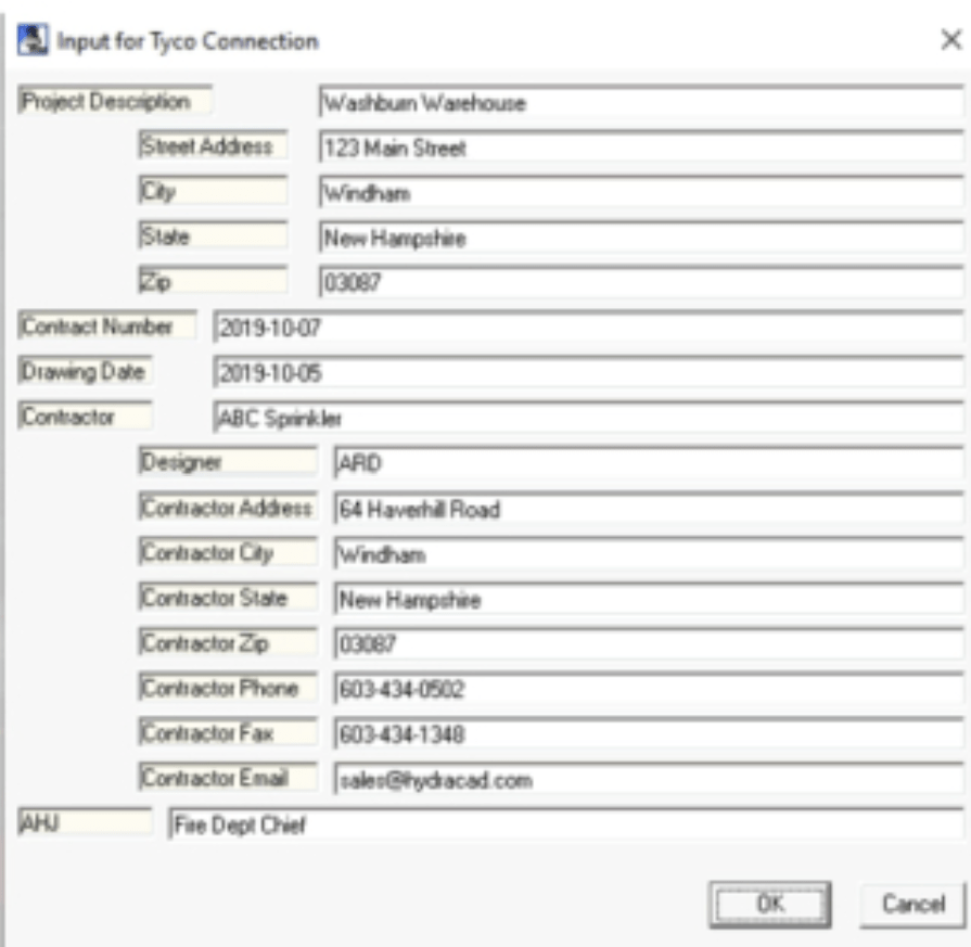
Select Yes if you have the Header Data already entered into an existing job. Select No to open the following dialog box where you can fill in the appropriate information and press OK when you are finished:
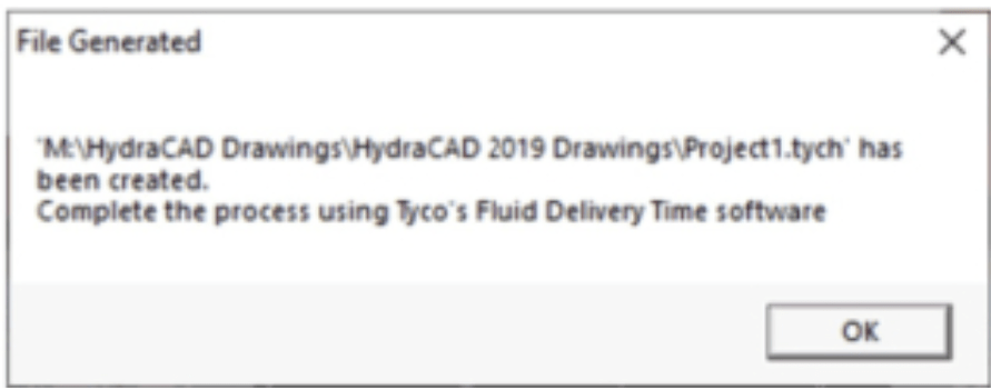
7. A message will appear indicating that the file was created. You should now be able to open the file in SprinkCAD FDT:
Way back in the olden days of 2014 I wrote a blog entry on BIM LOD. Sometime between then and now they snuck in a BIM Level 350, so I figured it was time to revisit this topic.
In the current context, there are six different levels of development that are defined by the American Institute of Architects (AIA). According to AIA, LOD outlines the design requirements at each stage.”
(even their nice picture doesn’t show six levels)
At LOD 100, which is the pre-design stage, the model consists of 2D symbols and the masses to signify an element’s existence.
At LOD 200, the elements are partially defined by outlining their approximate quantity, size, shape, and location.
By LOD 300, the elements are defined with exact dimensions and their relative positions bolstering precision.
LOD 350 describes the information about an element precisely and outlines an element’s relation and connection with other components.
LOD 400 outlines the basic information about the construction of various elements.
LOD 500, the model begins representing the real-life functions of elements in a real building.
There is a table of examples on their page as well..
Here’s where our software and it’s related applications fit in:
LOD 300
This is your standard AutoCAD / HydraCAD drawing. This is also what Navisworks fits into. And, if you export a HydraCAD drawing to Navis Manage model, it is a precisely drawn model (like the HydraCAD for AutoCAD drawing is) and is defined using exact dimensions, but information is only stored in a few elements
LOD 350
This is your standard HydraCAD for Revit model. Each element has information about the manufacturer, type of fitting, schedule, finish, material, or the like. It also covers Revit models that are generated automatically from HydraCAD for AutoCAD, but you may need to add additional information to some of the elements depending on what the BIM manager wants to see
PS –
LOD 100 is your basic pen and pencil estimate sketch LOD 200 is that estimate sketch done in HydraCAD for AutoCAD of even done using Sketch-it or another simple sketch program. It just means that things kind of look like what they are and there is a parts schedule or count LOD 400 models include all the instructions needed to fabricate and assemble particular elements, even the building LOD 500 is not used at this time
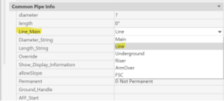
When a riser nipple is inserted a property is programmatically set identifying the riser nipple as a Line, Main, Arm-over or Underground for listing purposes. This can be ascertained by looking at the Properties of the rider nipple in question.
Most of the time, the way it is set is perfectly correct. On occasion, however, you might want to list a riser nipple a particular way. This most often happens when a riser nipple connecting a line to a main should be listed as a Main component due to a particular fitting or fabrication method, instead of the default listing configuration of Line. You could change it in the Properties or you can do it a better way:
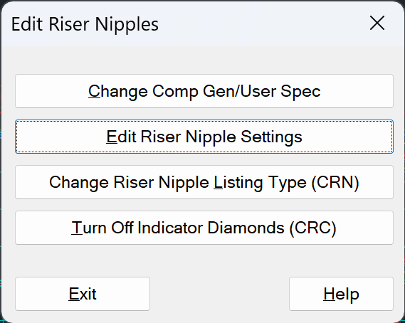
The Change Riser Nipple Listing Type command will make this easy. The Edit Riser Nipple command (ERN) on the riser nipple flyout of the Piping toolbar is where you will find it.
Type in ERN and pick the third item on that menu to activate the command.
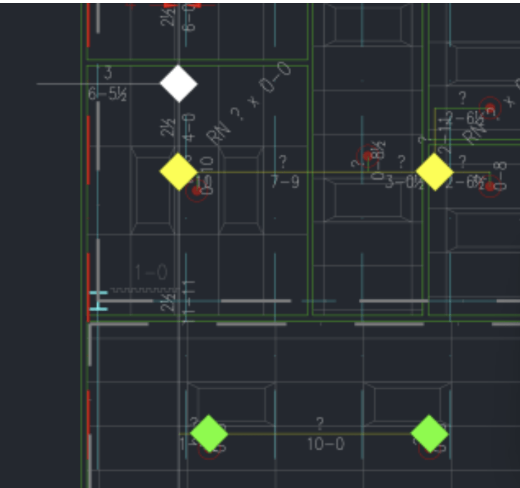
This command adds a colored diamond to each riser nipple. The color assigned denotes how the riser nipple is defined, for listing purposes.
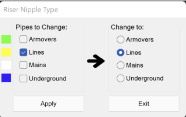
If you want to change one of those riser nipples, select the Pipes to Change and pick Apply. You will then be prompted to select the riser nipple(s) to change; the ones you select will be filtered based on your above selection.
The good news (for us at least) is that all our current versions of Hydratec software work well on it. I ran the update on my machine, and my already installed software worked just great. I have also run some of our install without a problem.
What’s the bad news? Nothing is broken, but a few big gripes about what they changed for no apparent good reason. They likely changed these to make Win 11 look different than Win 10, and more like a cell phone. That’s the worst reason I can think of.
Sadly, the list of things that were changed, but unhelpful has grown long enough to make a list, so here goes – click on the Item in the list, or scroll through to see them all:
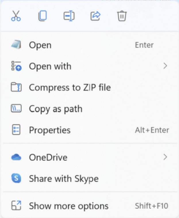
This is the menu that comes up when right-clicking on a file or folder. Along the top are icons for Cut Copy Paste Rename and Delete. I find these handy, but I just assume click on a word rather than use more brain neurons to think about the pic.
What bugs me is how much is missing. Where is New Folder, for example? I use WinZip a lot, but it’s not there either, nor are any third party tools like anti-virus tools.
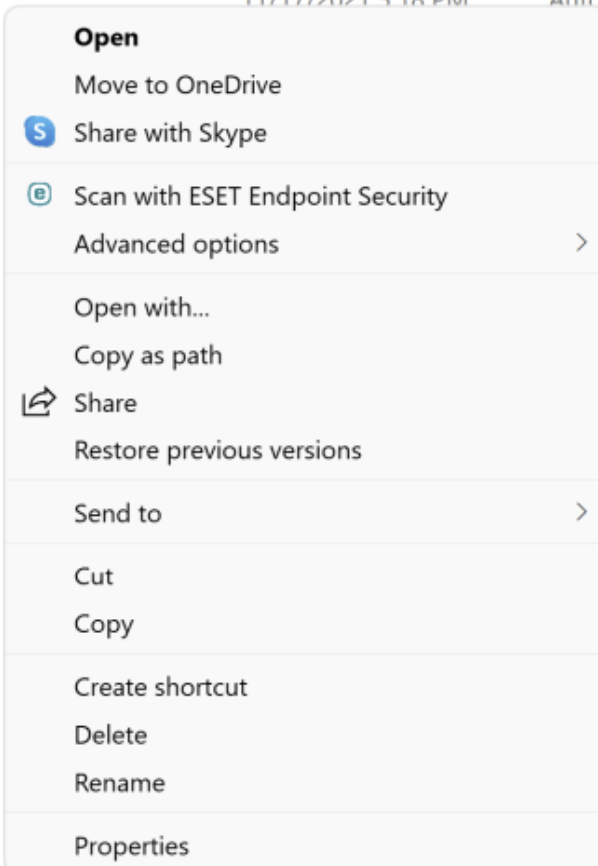
To get the expanded right-click menu, you need to pick Show more options. That brings up the ‘classic’ menu. so, an extra pick. Not convenient.
The Fix:
Go to the Command ‘DOS’Prompt by entering CMD in the Windows search bar.
Copy and paste the following command into the Command Prompt, then press Enter:
If everything goes right, it should say “The operation completed successfully.”
Close the Command Prompt window
Reboot the computer make the override take effect.
Item 2: Placement of the Windows Taskbar
The Windows Taskbar is now centered in Windows 11, just because:
The Fix:
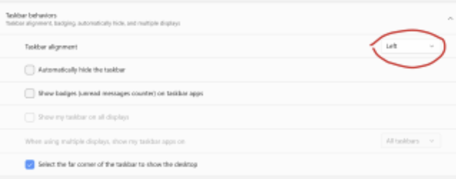
Right-click on any blank part of the Taskbar. Pick Taskbar Settings
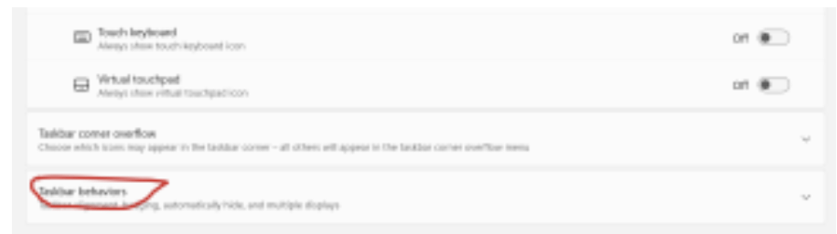
Pick Taskbar Behaviors at near the bottom of that resulting dialog
Pick Left from the Taskbar Alignment item. The taskbar will immediately move left
Item 3: The Windows Search bar
The search bar has been removed from Windows 11. It is now accessible by picking either of the two leftmost buttons, the Windows logo or the Search glass. Not a fan.
The Fix:There isn’t one
You can pick either of the two buttons, above and start typing your search term. Or, you can use the Windows logo key + S to search. Hovering over the search icon show the three most recently searched items.
You can remove the search icon from the taskbar by navigating to Settings > Personalization > Taskbar > Taskbar items and then turning off the Search option.
Item 4: Finding Programs
In Windows 10, you could pick the Windows Start button and navigate through the list to find the program you wanted to run. In Windows 11, yup, an extra click.
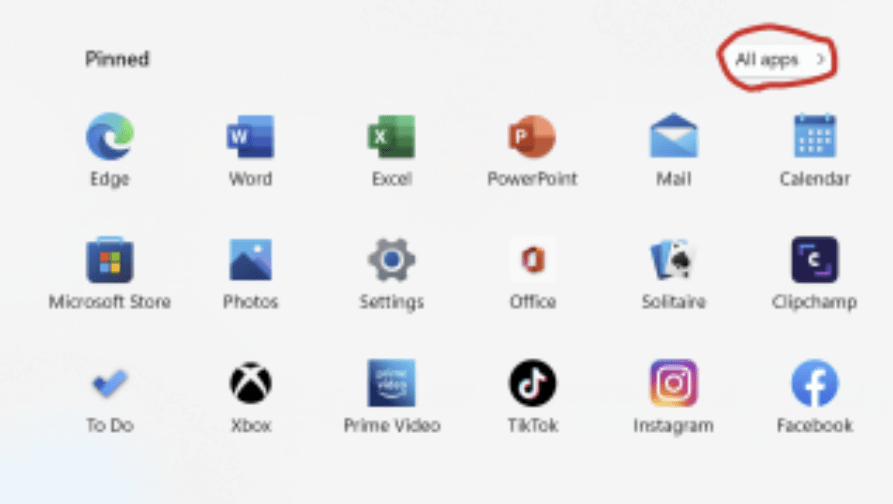
The apps you see when you hit the Windows logo key include some useful ones, but many are there to show how they know what the cool kids are using. Social media apps, Xbox and Prime Video. Blech. They really could have improved this if it was auto-populated with your most used apps. Nope.
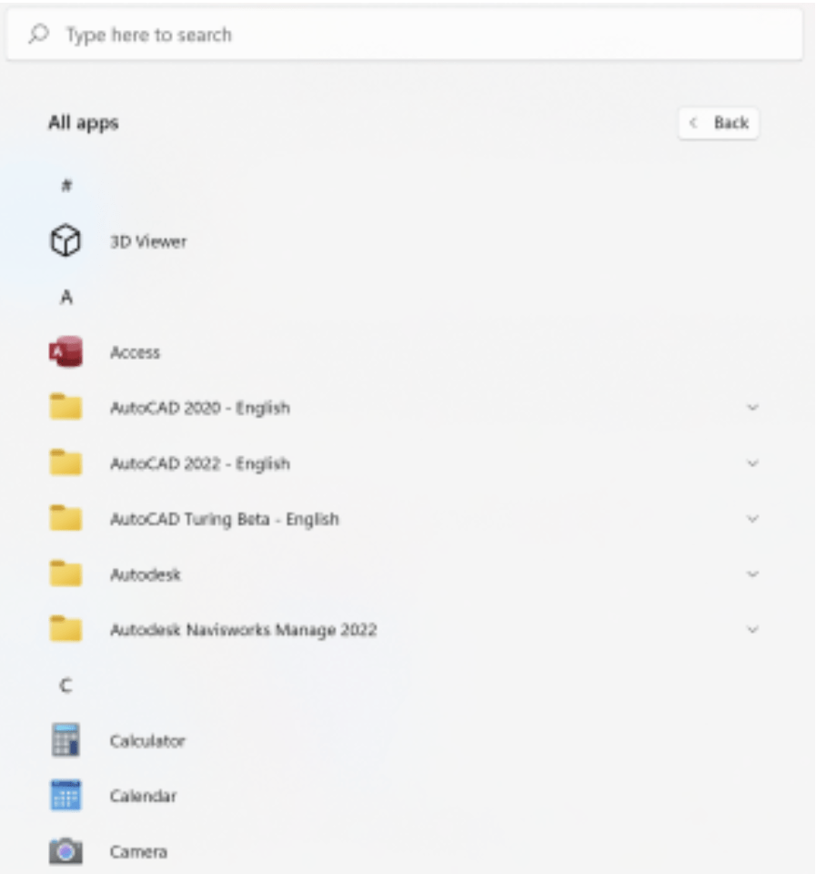
You again pick the Windows Start button, but then pick All apps to see what you used to see for free:
You can select an app from here, right-click and choose Pin to Start to get it on the default screen.
Microsoft even has a web page explaining the differences between 10 and 11. By the very act of writing this, they should have realized it was a bad idea to add an extra click. Find all apps and programs comparison
The Fix: – There isn’t one
Item 5: No Drag and Drop via Windows 11 Taskbar
Until Win 11, you could drag an item (like a file) down to the taskbar and pause for a moment over another application (like Outlook or Teams). The app would then open up and you could drop the item into something in that app. No longer! In Win 11 you get the No Go icon when you hover over the taskbar with dragged item in hand. Apparently they are using a new programming interface to rewrite the taskbar, but why they would not implement this is ridiculous.
So, you need to have both apps displayed and position them so that you can move the file from one app to another without losing focus.Ugh.
The Fix: A third party app. this one, available on the Microsoft Store, says it will do it. I have not tried it myself.
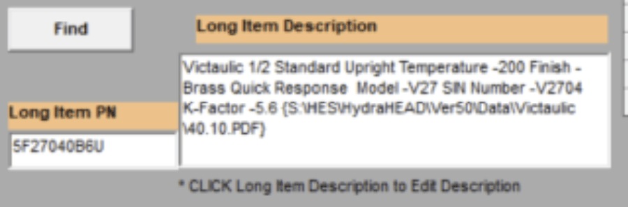
Taking into consideration the large number of sprinkler heads available, we decided not to clutter up the database and avoided predefining most of them. This means that you will often run an AutoList and find that the Miscellaneous tab in HydraLIST has a number of yellow highlighted head entries without a description. That is because the part number for those heads does not exist.
The printed instructions for this process can be found in the HydraLIST Manual on page 2-75. We will summarize below:
Steps
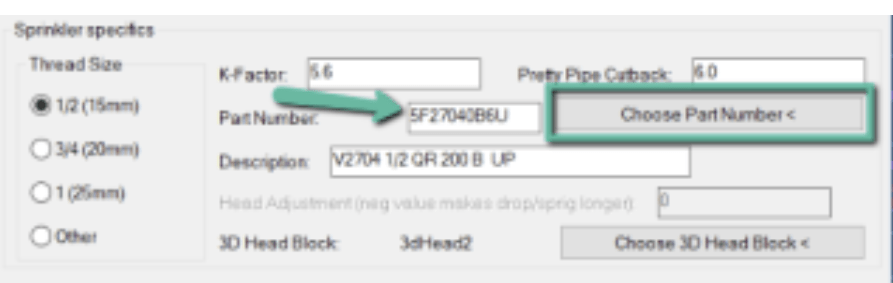
Go through all the usual steps to properly set up your sprinklers in the drawing, including choosing the part number.
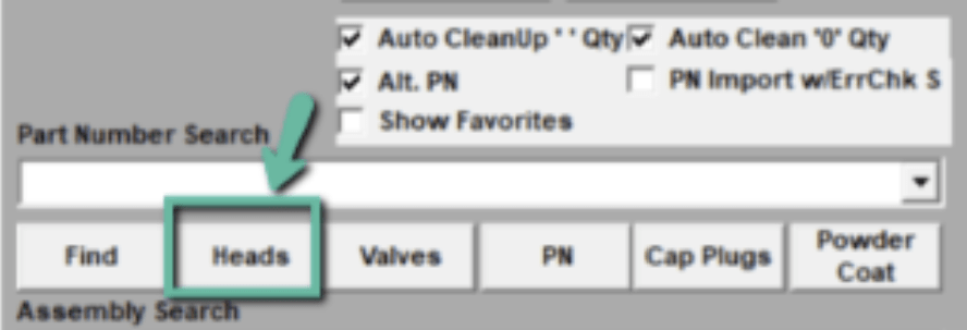
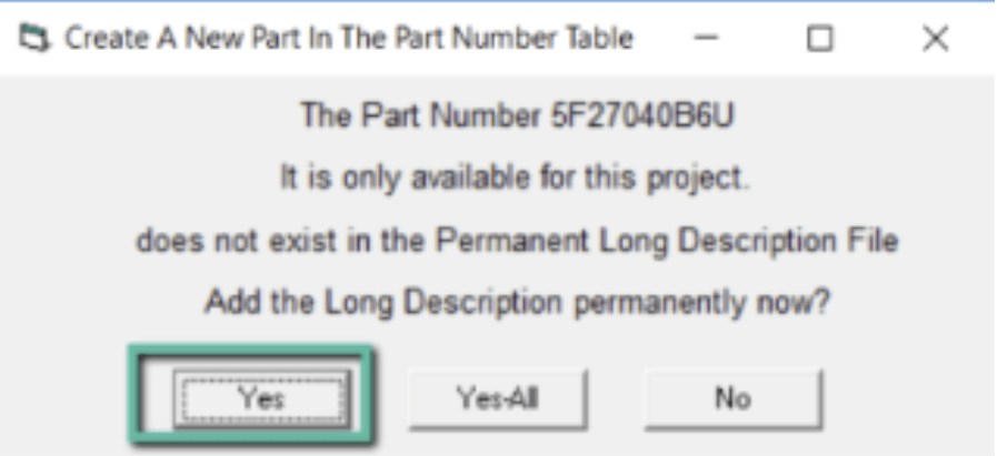
This time, you will have the option to add the head to the database, after you pick the Collect Selected Head Data button
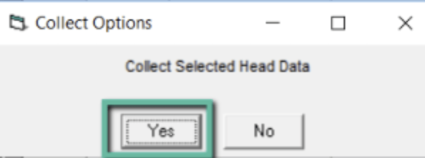
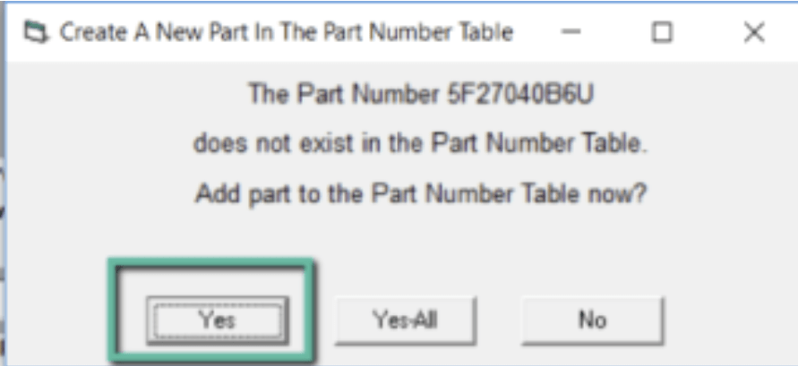
You will see a series of two dialog boxes. Answer in the affirmative
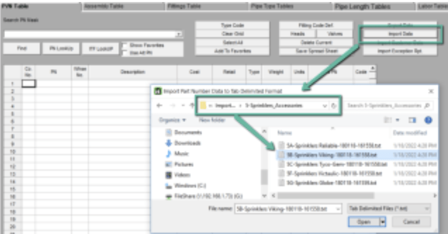
To share with others and distribute around the office: Copy the \HES\Hydlist\Ver50\Data\Setup folder from computer to computer, or copy just these two files:
Quick Assist is built into Windows 10 and allows for remote control connections to other computers. No downloads or other software needed!
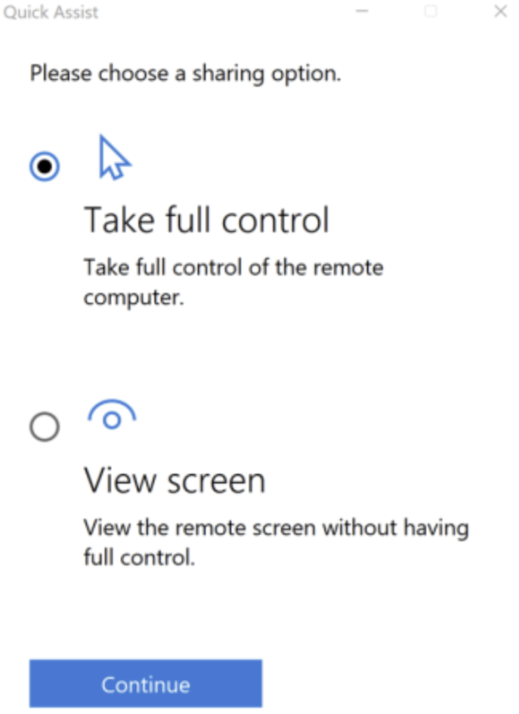
Type in Quick Assist at the Windows Search bar. You are given two simple options when it launches
If you want to take control or see another person’s computer, choose the Give assistance option. If someone wants to connect to you, use the Get assistance option
For example, Pick Assist another person. The app will connect to the netherworld and await confirmation with the other user
Have the other person launch Quick Assist as well. Supply them the six-digit code you see. Once they type that number in on their end (by typing it into the Code from assistant box in Step 1), you will be connected and given sharing options.
I never knew about this option until Googling about it today related to a customer reported problem.
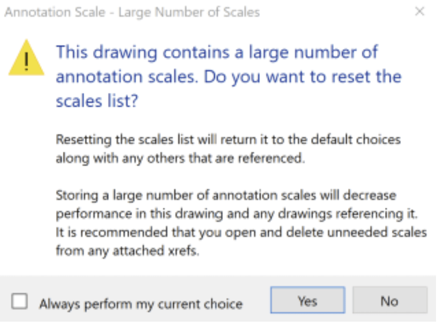
The problem was related to an old AutoCAD bug which allows a build up of a great number of annotation scales. This will cause a fatal error at various times in a drawing session. But, it won’t cause a problem on other machines if the following dialog were set to Always perform…
I had chosen that Always perform… option on my computer, so when reloading the drawing to get this screen capture and send it to our customer, the dialog did not come up, because I told it not to. How to reset it?
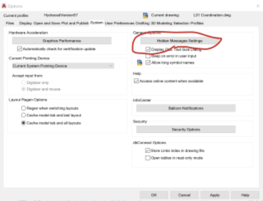
Go into AutoCAD Options and select the System tab.
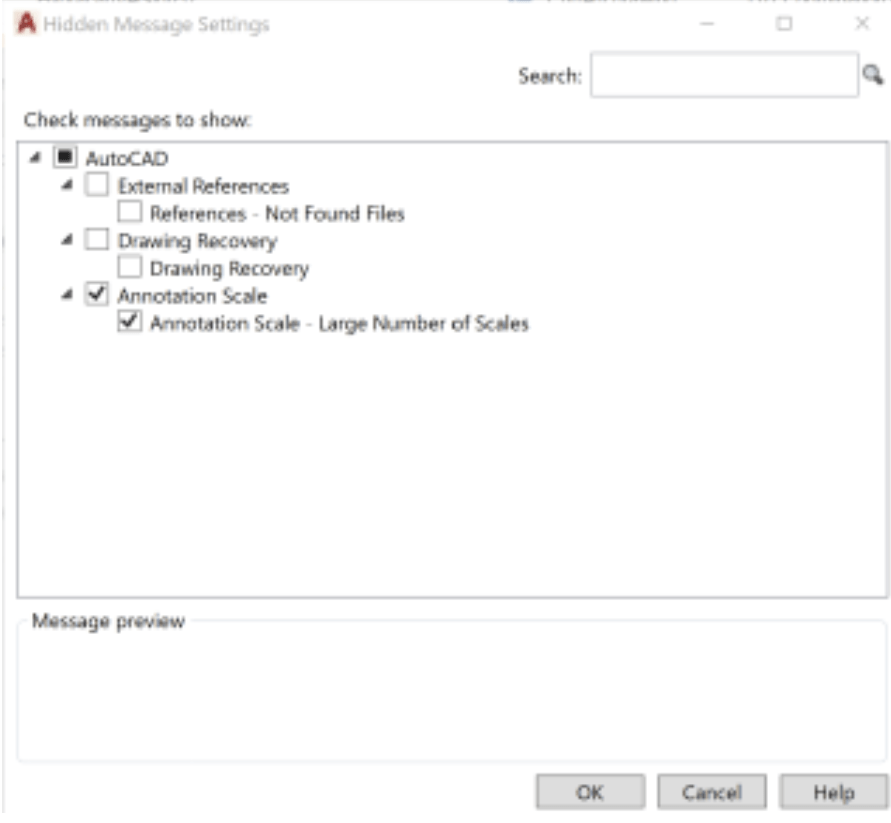
Select the Hidden Messages Settings button
Select the messages you want to un-suppress in the future. I really don’t know how many possible dialogs can show up here, but these are the ones I have, apparently, selected on my machine.
Many users prefer to use their own colors, linetypes, lineweights etc. when drafting. HydraCAD is set up to do just that. The only thing you cannot do is to change our layer names. But, you can add your own layers if you want.
The best overall approach is to set up your own template, beginning with a copy of our template. Our templates have all the layers in them that we need to run HydraCAD. If you start with our template, make your changes to it and save it as your own template, you are not overriding the rules of ours, and we aren’t stomping on yours after an update. This blog post explains how that should be done: Creating your own templates
Losing HydraCAD Layers
If you use AutoCAD’s PURGE command all unused HydraCAD layers (along with other unused layers) will be removed from the drawing. This is bad.
Rebuilding HydraCAD Layers
Use the Rebuild Layer command in the Hydratools->Tools dropdown menu. Or, type in RBL. This will rebuild all of our layers with their settings. It runs the layer script file that comes with HydraCAD, or the one you created, below.
Going forward, do not use AutoCAD’s Purge command. Instead, use our Super Purge, on the same menu as Rebuild Layers. Or, type in PUR. Super Purge does a deep purge of unused layer and blocks. It then runs our layer script file (layer.scr), which reinserts layers, blocks and dimension styles that HydraCAD requires to operate. Furthermore, it does an AUDIT to automatically fix drawing database errors.
Replacing our Layer Script with Yours
Open a drawing that has the layers set the way you like them. Then, pick Create Layer Script from this Drawing from the HydraTools->Options drop down menu. This will replace HydraCAD’s default layer script with yours.
To replace our settings and add yours, use the Create Layer Script from this Drawing command instead. The next time you use Rebuild HydraCAD Layers (RBL) or Super Purge (PUR), our layer script will be run with your custom settings, not ours. If you make a mistake and some of our layers are missing or the layer script will not run or locks up, it is easy to get back to our defaults. In that case, use the Restore Original HydraCAD Layers command just below the Create Layer Script from this Drawing command.
Making a Layer Script with Only Your Layers
This will allow you to retain your own added layers and not have them replaced when you run a HydraCAD update. Open a drawing that has the layers set the way you like them. Then, pick Create Layer Script from this Drawing from the HydraTools->Options drop down menu. This will replace HydraCAD’s default layer script (Layer.scr) with yours.
Then, pick the command named Edit HydraCAD Layer Script just above it. This allows you to edit this new Layer.scr file directly. Be careful in here, as script files are very sensitive to extra characters. However, if you want to make a new layer script with just your added layers, then use this command and do the following:
Keep the first line and the last lines in the new Layer.scr
Delete lines that refer to our layers and keep only those lines that refer to yours
Save this file with the name MYLAYER.SCR
Run the Restore Original HydraCAD Layers command. This will restore our Layer.scr to the shipped version
The next time you use Rebuild HydraCAD Layers (RBL) or Super Purge (PUR), our layer script will be run as well as yours.
To also have your layers listed under the HydraCAD Layers filter in the AutoCAD Layer panel, and have your layer descriptions there as well, then do this:
Locate the file named LAYER.DAT in the \HES\HydraCAD\Ver50\Programs\Version5# folder
Open this file with Notepad
Keep the first line and the last lines in the LAYER.DAT
Delete lines that refer to our layers and add in lines that refer to your layers, keeping the same format we have. You can also keep our lines and replace our terms with yours
Save this file with the name MYLAYER.DAT
The next time you use Rebuild HydraCAD Layers (RBL) or Super Purge (PUR), your layer names will be added to the HydraCAD Layer filter along with your descriptions.