
With HydraCAD for AutoCAD, you can draw a ‘regular’ HydraCAD system, and then create the Revit model for coordination with the BIM team on a project.
This requires a few things:
- You must have Revit on the computer using the HydraCAD for AutoCAD in order to make the conversion
- You must know the version of Revit that the BIM team is using to coordinate. Each version of Revit uses a different file format, unlike most versions of AutoCAD
- It is helpful to know the ‘common point’ that is being used by the BIM team to line up the models provided by each trade
If you have HydraCAD for Revit, then great! Because then you are actually drawing in Revit and don’t have to do anything.
Lining up the HydraCAD model with the ‘common point’ of the BIM model:
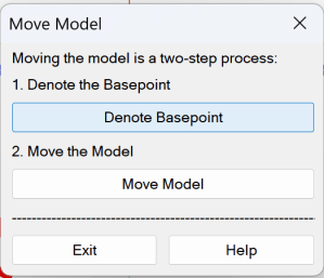
Step 1: From the Collaborate toolbar, pick the command named Move Model:
![]()
Step 2: Pick Denote Basepoint. The Project Basepoint is where the model will be moved to. The Match point is the point on the existing model that will be moved to the Base point.
For the Shape of the Box, select from Rectangular or Non-Rectangular. Use Non-Rectangular to define a boundary with multiple picks. The boundary will close automatically after you have made your picks and right-click to finish.
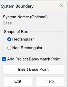
Check Add Project Base/Match Point. Select Insert Base Point.
When prompted to Pick a point for Project Base…, pick the point that will be the coordination point with other trades. Some users find it helpful to first insert some other type of item, such as a circle, at that point, and then insert the Base Point at the center of that circle. The Base Point can also be inserted at a precise location in 3D space by entering the coordinates in AutoCAD Properties.
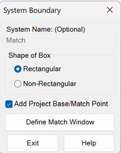
Start the command and select Denote Basepoint again. Check Add Project Base/Match Point. Note: Since the drawing already has a Basepoint inserted, the button now reads Define Match Window. To insert a different Basepoint, erase the one already inserted and start the command again. Select Define Match Window.
Step 3: Pick the Move Model button to make the move. The drawing won’t look any different after using this command.
Generating the Revit model:
Step 1: Elevate your drawing to 3D.
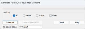
Step 2: Pick the Create RevitLink command from the Collaborate toolbar:
![]()
Step 3: Pick the version of Revit to go to and pick the Generate button
Step3a: If you get any errors during this part of the process, pick the Delete Elements button. You may have to pick it once for each error
Step 4: Pick Launch Revit MEP
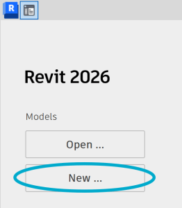
Step 5: Once Revit is open Pick New from the MODELS portion of the menu
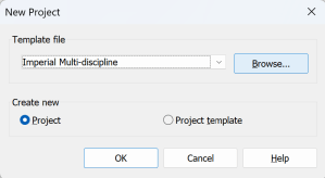
Step 6: Make sure Create new is set to Project, not Project template and pick Browse from the Template file selection.
Step 7: Browse to the C:\HES\Hydratec for Revit\Data\Families\20## folder, where ## if the version of Revit you are generating the model for
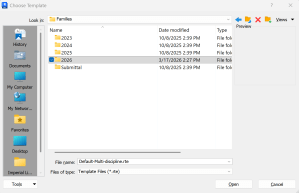
Step 8: Select the HydraCAD-Imperial_Default.rte (if using US unit system) or HydraCAD-Metric_Default.rte if Metric
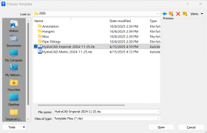
Step 9: Pick Open and then pick OK
Step 10: Pick Save to give your project a name and location
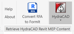
Step 11: On the Addins tab, select the Retrieve HydraCAD Revit MEP Content item from the HydraCAD button
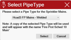
Step 12: If you are asked to pick the Pipe Type for the mains and Lines, do so
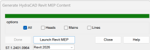
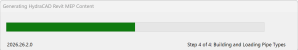
Step 13: This will begin Step 2 of the conversion process. This process will take at least a few minutes to complete, possibly up to 10 to 20 minutes or longer
Step13a: If you get any errors during this part of the process, pick the Delete Elements button. You may have to pick it once for each error
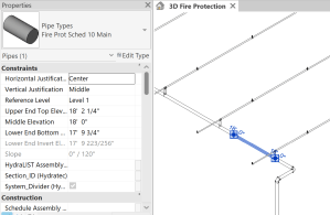
Step 14: After the conversion is complete, you can save and send the .RVT file to whomever you want. If you want to view the fire sprinkler piping, use the Project Browser to select Views – Coordination – Fire Protection – 3D Views – 3D Fire Protection
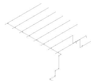
Step 15: This will show the model that was created. Each element and head has been given information as to its type or manufacturer. Save this model and share it with the BIM team

Leave a comment