After downloading a file, it is often Blocked. You must right-click on it, pick Properties and then check the Unblock item: But doing a dozen or more files gets old, real fast. I just learned a way to Unblock a batch of files at once. It involves using PowerShell, a Microsoft tool that is a…
If you want to use a new type of hanger, or are a fab shop that gets a job from a contractor that uses a hanger type that you do not have, it is easy to add that new hanger type to your own machine. A hanger is an assembly, and an assembly is just…
Recently our previous blog service (Typepad) ended their business – so, we have a new home. It will take a bit to get images back and displaying properly, but we are working on it! Final pageview count of original Typepad blog: 387,232
Considering that Manage costs so much more than Simluate. why get it? This comparison matrix helps you figure it out. While you can buy Simulate and upgrade to Manage,you won't get full trade-in value. And what abot Freedom?
On another note, if you press Ctrl+Z to undo something, you can also type Ctrl+Y to redo it.As I fortuitously remembered while typing this post and almost wiping it out.
If you need to Repair or Reinstall AutoCAD, or if HydraCAD is not loading properly, then you will need to reconfigure AutoCAD to look at the HydraCAD settings. Fortunately, this is quite easy:
Windows 7:
1. Close AutoCAD/HydraCAD 2. Pick the Windows Start button 3. Pick All Programs 4. Pick Hydratec Version 50 Software 5. Pick Configure AutoCAD for HydraCAD V##, where ## is 55 or 56 or whatever your are using 6. Reopen HydraCAD and try it out
Windows 10:
1. Close AutoCAD/HydraCAD 2. Begin Typing Configure AutoCAD for HydraCAD V## (where ## is 55 or 56 or whatever your are using) into the Windows Search box. Run the program. 3. Reopen HydraCAD and try it out
Another one from our friend Larry Howell at L&K Fire Protection (Marion, Illinois)
If you get a background drawing that has AEC objects in it, you might find that drawing takes forever to run through the AutoCAD FLATTEN command, or never completely flattens. Larry has discovered a command that will handle it for you:
Open drawing with objects, I had 5 floors so it worked better wblock the floors separately
Open new Wblock drawing and enter “-ExportToAutoCad or AECtoACAD”
Left the “filename” default and hit enter
Made a new drawing “ACAD-*”
Converted a lot faster than flatten, converts AEC but leaves “REGION OBJECTS” but made a good clean drawing.
This is a blog posting of the information sent in a recent newsletter, archived here for easy access.
There are still many questions about Revit and BIM and what is required for what and by whom. What follows is a simple list of facts that may help explain it to you.
If a project up for bid requires that you produce Revit drawings and you are wondering if you can fulfill that requirement; the answer is yes if you have HydraCAD Version 51 and Revit MEP Suite
Revit is not AutoCAD. It is a separate Autodesk product that is quite different from AutoCAD
HydraCAD V51 can produce 3D piping, hangers, fittings, couplings, earthquake bracing, sprinkler heads and zones of influence
Architects and building owners have been sold on the usefulness of Revit when building modeling and reference information are important. This has trickled down to the rest of us
Revit cannot be programmed like AutoCAD can. Therefore it is not possible at this time to create an add-on to Revit like HydraCAD
Drawing in Revit is very slow and time-consuming. Some things cannot be drawn at all, like flanges and welded outlets. This limits it usefulness for designers
Because of the above, it is necessary to draw in AutoCAD or AutoCAD MEP to be productive and automatically create the Revit model from there
HydraCAD V51 can produce the Revit/BIM model necessary for coordination
You will need Revit MEP Suite on the same computer as HydraCAD V51 to produce this model
Nothing special needs to be done to produce a Revit model. You draw the same way you have been in V51. When you are ready, you pick the Create Revit MEP Link to produce the model
The model produced by HydraCAD contains Revit native objects
Any AutoCAD can be upgraded to Revit MEP Suite – the only Revit product supported or needed
Revit is capable of clash detection, but only with projects submitted in Revit
If a project up for bid requires that you produce drawings than can be clash-detected in Navisworks and you are wondering if you can fulfill that requirement; the answer is yes if you have HydraCAD Versions 50 or 51
Navisworks can do clash detection of drawings produced across a range of drawing packages – AutoCAD, Bentley, etc.
Navisworks comes in two flavors. The Simulate flavor will let you produce Navis files, but not do clash detection. The Manage flavor will allow you to do both. Both flavors come in stand alone and network configurations
Nothing special needs to be done to produce a Navis file. You draw the same you you have been in V50 or V51 and press the Make Solid Pipes command
We offer two hour webinars for companies that want to see how Revit works with HydraCAD. We can also show you how to produce a Revit file by using your own drawing. Contact us for cost and details.
We can We have produced a PowerPoint presentation to see how HydraCAD works with BIM and Revit. This particular presentation emphasizes our ties to Victaulic and references some of the tools that they have that are also BIM compatible: BIM/Revit/HydraCAD PowerPoint Presentation.
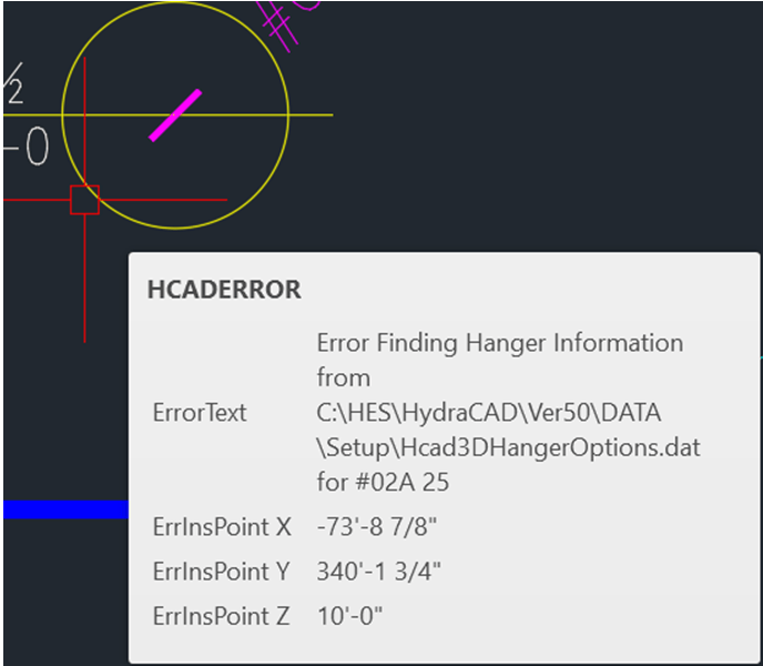
From a customer (RM): I want a Sammy Screw hanger type (HydraCAD’s #02 and #02A) to show up in 3D when I use Create 3D Hangers. Instead, I get an error stating that it cannot find the 3D hanger information for that type:
The data file for creating 3D hangers is located in the \HES\HydraCAD\Ver50\DATA\Setup folder. It is named Hcad3DHangerOptions.dat file.
1. Locate the file and open it by double-clicking on it. It should open in Notepad automatically. If not, pick Notepad from the list of options that appears.
2. Select the data from the file that is similar to hanger you are building and pick Copy
3. Go to the bottom of the file and paste that data, or paste it numerically in the sequence if you would rather do that
4. Modify the data to match what you are looking for
5. Save the file
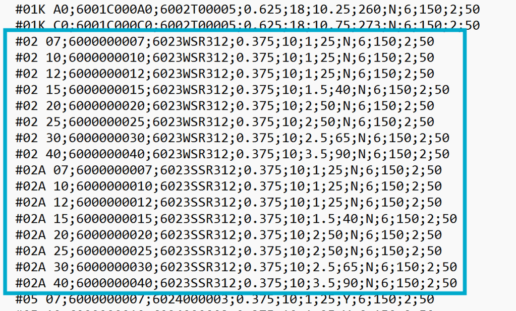
Example
Notice that the second line of this file explains what each column, separated by a semi-colon, is used for
In this example, the customer created the data for both the #02 and #02A Sammy Screws by copying and existing hanger type and modifying that. This is recommended because the format and syntax of the entries are critical.
Save the file. Also, I suggest you make a backup of this file incase a future update replaces it.
Reference – The Hcad3dHangerOptions.dat fields and their use
Hanger num & size#02 07 (Hanger assembly number preceeded by # sign, space, diameter code)
Bottom connection PN 6000000007 (Part number for ring from the HydraLIST data entry)
Top connection PN 6023WSR312 (Part Number for Clamp from the HydraLIST data entry)
Rod dia. (inches) 0.375
Rod dia. (mm) 10
Bottom offset (inches) 1
Bottom offset (mm) 25
Show Connection Zone N (Connection Zone is BIM interference zone
Autodesk has a Navisworks NWC Export Utility that lets you create Navis content directly from the HydraCAD 3D model without having Navisworks and without the need to create the Solid Pipes drawing.
Install the linked tool, elevate to 3D and then type in NWCOUT. This will create a Navisworks cache file that can be opened by those who have Navisworks for viewing and/or clash dtection purposes.
No one topic seems to cause more consternation than Object Snaps. Here is the what and why of why we do what we do:
We need to have object snaps set for a certain number of commands to ensure that the drawing is connected properly. Many users feel that we willy-nilly overwrite their osnaps, i.e. – don't put them back the way we found them. This is not true. The following rules should explain how you can keep your osnaps:
1. ALL HydraCAD commands are intended to return your default osnaps to you after you complete the command. The only exceptions are the Line and Main commands because these two commands are 'endless' commands (we don't know when they are done). If you find any exceptions, please let us know and we will lock them down.
1A. Right now, the Rapid Pipe commands will not reset your osnaps if you use the Escape key to exit these commands instead of using Enter to exit them. We are working to change this behavior.
2. You can turn off the HydraCAD object snaps and use your own for most of the important commands by picking the Options submenu from the HydraTools pulldown menu. then, pick Use Your Own Object Snaps
3. The Sprinkler, Piping and Hanger toolbars contain their own osnap buttons to be used for the commands found in those toolbars. These effectively give you a second set of osnaps, preserving your basic AutoCAD osnap for when those commands are done. These only need to be set once per drawing.
4. We have been steadily reducing the number of default osnap settings for non-critical commands. These will be entirely up to you to set.
5. We have added two buttons to help make using your default osnaps easier. On the HydraCAD Utilities toolbar there are two commands: Save Osnap (OSS) and Restore Osnap (OSR). These allow you to set a default osnap and bring it back whenever you want.
I realize this is a sensitive topic for some of you but we do need to set some sort of base osnaps so that users (new ones, especially) can 'just draw' and have a reasonable chance of getting a calc or list out without all kinds of drawing errors. Believe me, we've tried it the other way and it hasn't worked.
If you spend a lot of time searching through parts when in the Miscellaneous tab, consider doing this:
Search for parts you use over and over again and narrow down the sizes/specifics/manufacturers of those you use most.
Enter a quantity of 1 next to each part
Pick the Clean Up button to clear those you did not select
Pick the Save List button and type in a file name like 'usual stuff' or 'typical loose material'
Next time you stock list pick Load List, select the file you want and then adjust the quantities as needed. Just zero out the items you don't want. You can even create folders to keep them all in.
Thanks to John Hulett of Western States Fire Protection for handing over this tip.
Many times background drawings have large blocks contained of many elements, and those elements may have many different colors. How to get them all to be the same color you might ask. Or linetypes
1. Pick the Change to ByLayer command from the AutoCAD Modify pulldown menu
-or-
2. Pick the Set to ByLayer button on the Home tab/Modify panel from the ribbon menu
-or-
3. Type in SETBYLAYER
Then select the objects to change. Then enter Y when asked to change ByBlock to Bylayer. Lastly, enter Y if you want to include blocks.
My crystal ball say that I forsee adding a button to access this on our Clean up Backgrounds toolbar in a future update.
From a Customer: "Is there a way to set multiple floor elevations in 3D so the elevation tags and ceiling hts will be set correct from each floor elevation?"
Yes (you didn't expect me to say no, did you?). Using the Structure Elevations (TOS) command from the Steel toolbar (or Elevate ribbon panel) use the Floor Elevation button to specify this. You can even use it to compensate for those structures where the top of steel elevation is adjusted + or – for the joists