The H-Factor

Reducing Entropy

Recent Posts

Adding Hanger Types to HydraLIST

If you want to use a new type of hanger, or are a fab shop that gets a job from a contractor that uses a hanger type that you do not have, it is easy to add that new hanger type to your own machine. A hanger is an assembly, and an assembly is just…

Welcome

Recently our previous blog service (Typepad) ended their business – so, we have a new home. It will take a bit to get images back and displaying properly, but we are working on it! Final pageview count of original Typepad blog: 387,232

Using a Non-Standard Pipe Type in HydraCALC

A customer called today asking how to enter a 1″ black plastic underground pipe for the calc. This particular situation sounded unique enough that I did not tell him to add that pipe type to our database, as I would have if he expected to see this pipe type used repeatedly. I told him to…

September 2026
M T W T F S S
 123456
78910111213
14151617181920
21222324252627
282930  
  • If you are using Naviswork Manage to do clash detection, then we have the tool for you! HydraCAD has a tool that will put a yellow error circle at each location that a clash occurs. Use the Navisworks Toolkit button on the Collaborate toolbar (below)

    Then, export your piping to Navis and run a clash check. Then, switch to the Report tab and write a report to Text format, with at least Clach Point and Item Path checked.

    Write this report to the C:\HES\Temp folder and name it HCAD_CLASH_DATA.TXT. Leave Navis open and then pick the Import Clashes Into Drawing option in the Navis Toolkit referenced above. Error bubbles will appear at the conflict locations. Hover over one of the errors to get information about that error:

    Note: There is a Help document in the toolkit to refer to. There is also a Video for this process! You may need to download the full video from our support site, however.

  • HydraCAD Version 52.2/51.12 added a new command to the Piping toolbar – Size Pipe by Schedule. This command will apply a sizing schedule to the line or main picked, along with all the lines or mains attached to it.

    – Icon for Size Pipe by Schedule

    This command s easy to use. Put your model into 3D mode, then pick this command.

    Set your options and pick Continue. The Pipe Schedule screen will then come up. Set your sizing choices there as well. Then, select the pipeto be sized. Any pipes connected to that pipe will also be sized.

    Armovers will be sized properly of they are drawn in the new armover layer (SPRKDAT4)

  • What is LOD? It is 'Level of Development', a BIM pseudo-standard that specifies the level of completeness of a drawing/model. HydraCAD is capable of fulfilling all these levels, although most contracts (for now, at least) specify LOD 300 as the current goal. The following is from KalBlue:

    "BIM has been outlined into five levels.  These levels help define consistent expectations throughout the building lifecycle from planning through design and construction and ultimately the building lifecycle. There are five defined LOD standards per the AIA E202 document.  LOD 100 – 300 have a reference to the traditional 2D project delivery method while levels 400 and 500 are specific to the BIM process.  

    Level of Development – LOD is generally defined as follows:

    LOD 100 – The equivalent of conceptual design, the LOD 100 model usually consists of overall building massing designed to perform whole building type analysis including volume, building orientation, square foot costs, etc.

    LOD 200 – Similar to schematic design or design development, the model would consist of generalized systems including approximate quantities, size, shape, location and orientation.  LOD 200 models are typically used for analysis of defined systems and general performance objectives.

    LOD 300 – Model elements equivalent to traditional construction documents and shop drawings.  LOD 300 models are well suited for estimating as well as construction coordination for clash detection, scheduling, and visualization.  LOD models should include the attributes and parameters defined by the owner in the BIM deliverable standard.

    LOD 400 – This level of development is considered to be suitable for fabrication and assembly.  This LOD is most likely to be used by specialty trade contractors and fabricators to build and fabricate project components including MEP systems.

    LOD 500 – The final level of development represents the project as it has been constructed including as-built conditions.  The model is configured to be the central data storage for integration into building maintenance and operations systems.  LOD 500 models will include completed parameters and attributes specified in the owner's BIM deliverable specification."

  • So, you've drawn dashed/dotted/hidden lines in Model Space and they look just great. But, you go to Paper Space and they are all solid. What is going on?

    The setvar PSLTSCALE is what is going on. It's default setting is 1, which means the linetype scale being applied is based on the scaling of the Viewport, not by the Model Space (or Paper Space) LTSCALE

    From AutoCAD's Help file:

    0 – No special linetype scaling. Linetype dash lengths are based on the drawing units of the space (model or paper) in which the objects were created. Scaled by the global LTSCALE factor.


    1 – Viewport scaling governs linetype scaling. If TILEMODE is set to 0, dash lengths are based on paper space drawing units, even for objects in model space. In this mode, viewports can have varying magnifications, yet display linetypes identically. For a specific linetype, the dash lengths of a line in a viewport are the same as the dash lengths of a line in paper space. You can still control the dash lengths with LTSCALE

  • Occasionally, we are faced with situations where we try to install a program and Windows says it is already there, but we think it isn't, and we can't find it in Programs and Feature in Control Panel. Or, we are trying to uninstall a program, and Windows errors out saying it is not there(!)

    The tool to use is the Windows Program Install and Uninstall troubleshooter. You can select progrm to install and to uninstall.


  • This topic also came from my co-worker Paul, who was asked to assist a customer with his question:

    From the Customer: Although we may stocklist hangers to
    ensure we have a good amount of material, we do not actually fabricate any
    hangers…Is there a way to have hangers marked as
    “loose” from the get go so they don’t print on the misc “fabbed” report AND
    show up as “L” in the inventory transfer file?

    Paul's Response: Hanger material is
    assumed to be fabricated by default. To make the hanger
    material report loose:

    1. Open the Assembly Table
    in the General Data area
    2. Check the boxes that say
    'Use Hanger Grid' and 'List as Hanger'
    3. Enter the letter L
    in the M/L column and save the assembly

    This will make all the
    material in the assembly list as loose

    Hangers

    Below is a list of
    options for the M/L column, from the HydraLIST manual:

    Hangers2


  • This topic came from my co-worker Paul, who was asked to assist a customer with his problem:

    From the Customer:  I either want the nipples
    and associated fittings to be entirely loose (listed on the “loose” picklist
    and eliminated from the lines fabrication sheet), or entirely made on (leave
    them in the fabrication sheets but add the items to the “fabbed”
    picklist.  As it is, there is confusion as to what is actually “loose” and
    what is “pulled on”, as well as inventory issues associated with the missed
    fabricated items.

    Paul's Response: Pick the Process buttons, then pick the general Setup Tab and check the box that says Count Make On’s for
    Nipples
    . If this is checked, then
    nipples and fittings for nipples are treated as fabricated material. If unchecked
    nipples and fittings for nipples are treated as loose material.


    Nipples

  • Tired of always picking the same template every time you open AutoCAD or start a new drawing? There is an easy way to set this:

    1. Right-click on the cammand line and pick Options or Pick Tools->Options to get into AutoCAD's settings

    2. Pick the Files Tab

    3. Find Template Settings and expand that

    4. Select Default Template File Name for QNEW

    5. Click on the value there now (None) and pick Browse and browse to the template you wisgh to begin in each time. That's it!

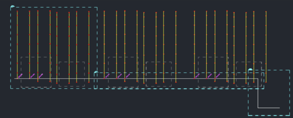
  • If you have a large drawing, we have long recommended that you use System Boundaries to break up the drawing for processing. But what if the system to be calculated stretches across other systems? You can still use boundaries, just use more of them, and make them isolate the main (more or less). See below:

    In this building, I drew three boundaries, one around the system at left, and two around the main and underground. They can overlap, and they can contain extra pipes that do not feed the deisred system. When you calculate, or list or go to 3D, just select all three and it will work just fine. Do not worry if there are some extra pipes inside those windows, they wil get filtered out by the software.

    PS – One little known thing about boundaries is that the name given to them means nothing to the program. When it comes time to select boundaries, the programs refer to them not by name, but by the fact that they were selected.

  • A tip from Joe O. at Troy Sprinkler:

    I just came
    across something really cool that I did now know and thought it might be a good
    one to pass along.

    I wanted to
    copy objects and then rotate the objects.  Essentially having the same
    group of objects but rotated at a different angle.  It’s already built
    into the AutoCAD Rotate command!

    1. Start the
    Rotate command

    2. Select the
    object(s)

    3. Specify the
    base point

    4. Notice the command line options – at the next
    prompt choose C for copy

    5. Specify the
    rotation angle

    I don't know what version of AutoCAD added this option, but it is pretty cool…